
featured products
Abracon
FIXED IND 47UH 2.8A 62 MOHM TH
$3.3
2574 available
Abracon
FIXED IND 220UH 2.8A 150 MOHM TH
$3.92
2397 available

Abracon
FIXED IND 560UH 4A 210 MOHM TH
$6.08
1996 available
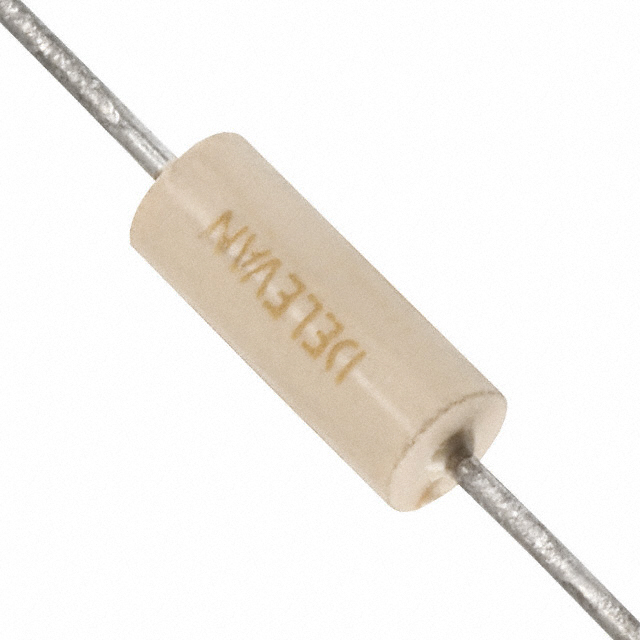
API Delevan
FIXED IND 180NH 1.12A 120MOHM TH
$2.4
2100 available

API Delevan
FIXED IND 39UH 125MA 3.6 OHM TH
$3.17
2100 available

API Delevan
FIXED IND 330UH 45MA 28 OHM TH
$3.51
2100 available
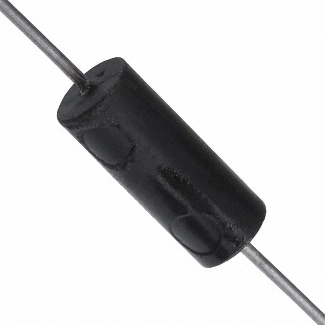
API Delevan
FIXED IND 27UH 265MA 1.19 OHM TH
$6.29
2582 available
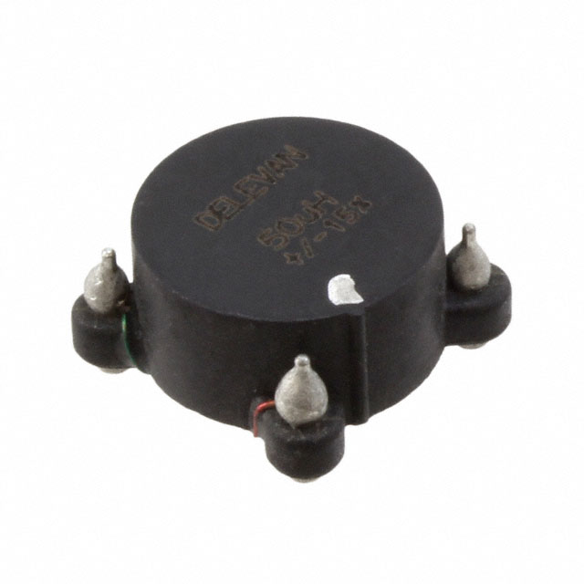
API Delevan
INDUCT ARRAY 2 COIL 33UH SMD
$9.78
1600 available

API Delevan
INDUCT ARRAY 2 COIL 150UH SMD
$9.78
1600 available

API Delevan
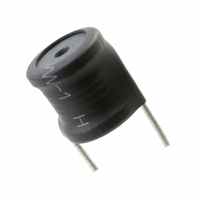
FIXED IND 560UH 1.15A 504MOHM TH
$5.67
1641 available
API Delevan
FIXED IND 10UH 6.44A 16 MOHM TH
$5.67
2218 available

API Delevan
FIXED IND 22UH 5.26A 24 MOHM TH
$5.67
2070 available
brand


AIRD-01-470K
AIRD-02-221K
AIRD-03-561K
1025R-02K
1025R-58K
1025R-80K
1641R-273K
4448R-122L
4448R-30L
4590-564K
4590R-103K
4590R-223K
DC630R-682M
1538M12
155C
159ZB
193H
195E50
1140-390K-RC
2000-470-H-RC
2300HT-120-H-RC
2300HT-150-V-RC
2304-V-RC
5720-RC
9230-10-RC
PM2110-820K-RC
PM2120-271K-RC
PM2120-561K-RC
PM3604-5-RC
SRF1280-1R5Y
SRF1280-3R3Y
SRF1280A-102M
HLC021R8BTTR
L0201R68AHSTR\500
L04022R2BHNTR
TYS40306R8M-10
60A273C
S34603
1974BE
2127E
2172BE
2172G
2175E
6001E
6104-6 1-2E
6104-EM-119E
ERA-S15J271V
ERA-S15J561V
Copyright@2025 All Rights Reserved