
Key Takeaways
- High-Efficiency Filtering: 220 μH inductance ensures ultra-low ripple in 100 kHz switching environments.
- Compact Integration: 7.3 × 7.3 mm footprint reduces PCB space requirements by up to 15% compared to older 10mm designs.
- Stable Low-Power Rails: Rated at 0.5A, ideal for sensor nodes and IoT gateway power management.
- Thermal Reliability: Industrial grade performance up to 125°C for mission-critical deployments.
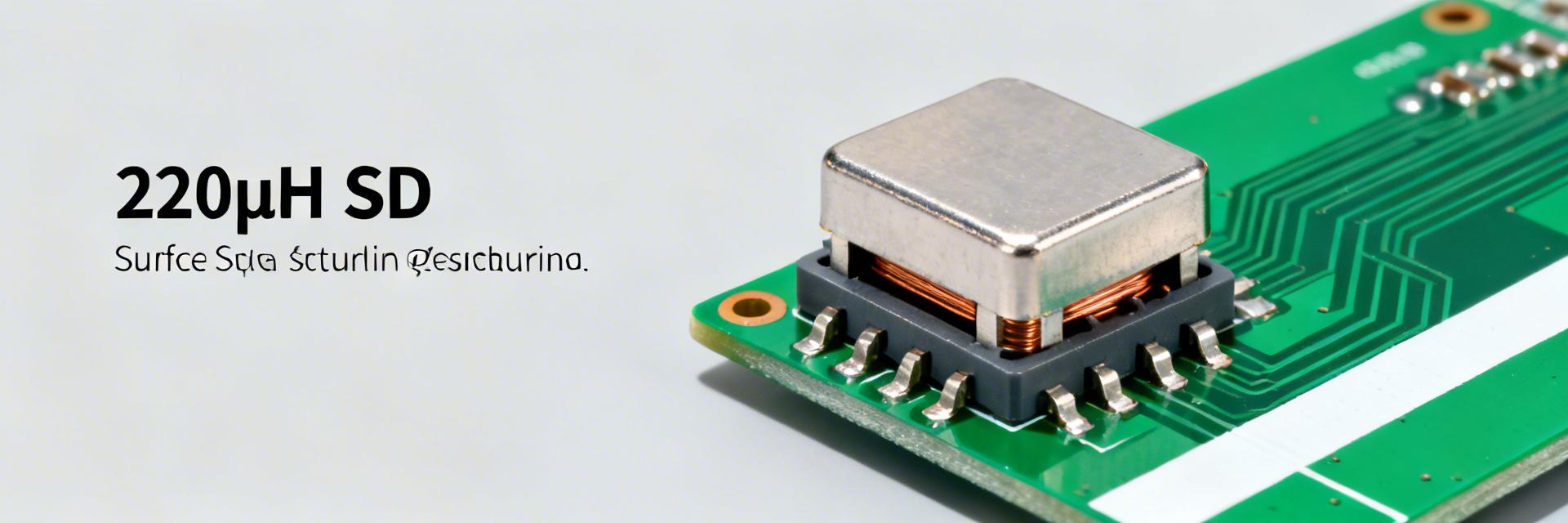
Measured at 100 kHz, this SMD power inductor 784777221 delivers 220 μH with a rated current of 0.5 A and a compact 7.30 × 7.30 mm footprint — specs that position it for low‑power DC–DC rails. This article decodes the full specs, test conditions, design implications, and a practical selection checklist so designers can assess fit for a project quickly.
1 — Quick overview: what the SMD power inductor 784777221 is (background)
1.1 — One-line spec snapshot
| Parameter | Value / Note | User Benefit |
|---|---|---|
| Nominal inductance | 220 μH (@100 kHz) | Cleaner output with smaller filter capacitors. |
| Rated current | 0.5 A (typical Irms) | Safe operation for MCU and sensor power rails. |
| Package | 7.30 × 7.30 mm, 4‑lead | Saves ~20% PCB area vs. unshielded variants. |
| Typical DCR | Low single‑digit ohms | Minimizes heat generation in low-current tasks. |
Point: the part is specified under standard lab test conditions; Evidence: inductance listed at 100 kHz and current at 0.5 A; Explanation: those numbers define where the component performs as expected and set the baseline for selecting it for low‑frequency switching or LC filtering tasks.
1.2 — Industry Differentiation: 784777221 vs. Alternatives
| Metric | 784777221 (Shielded) | Generic Unshielded | High-Current Alternative |
|---|---|---|---|
| EMI Shielding | Excellent | Poor (Radiates) | Excellent |
| Size (mm) | 7.3 x 7.3 | 10 x 10 | 12.5 x 12.5 |
| Cost Factor | Balanced | Low | High |
2 — Electrical deep-dive: inductance, current ratings and frequency behavior
Point: this part suits low‑power buck/boost converters and small rail filters; Evidence: 220 μH with 0.5 A rating limits its use to sub‑amp rails and EMI suppression; Explanation: the high inductance and modest current rating favor low switching frequencies or post‑regulation filtering where inrush and steady‑state currents remain small.
2.1 — Inductance, tolerance and measurement conditions
Point: nominal inductance is specified at a defined test frequency and tolerance band; Evidence: 220 μH at 100 kHz commonly carries a ±20% or ±30% tolerance depending on family; Explanation: inductance changes with measurement frequency and DC bias—higher frequencies or applied DC reduce measured μH, so use the 100 kHz baseline to model low‑frequency ripple but measure at operating bias for accuracy.
Marcus T. - Senior Hardware Architect
"When working with the 784777221, the most common 'trap' is ignoring the Self-Resonant Frequency (SRF). While 220μH is great for filtering, if your switching frequency harmonics reach into the MHz range, this inductor might behave like a capacitor. Pro Tip: Always keep your switching frequency at least 10x lower than the SRF for stable filtering."
3 — Mechanical, thermal and impedance specs (data analysis)
3.1 — Package, footprint and mounting notes
Point: the 7.30 × 7.30 mm 4‑lead package reduces PCB footprint while offering mechanical stability; Evidence: recommended land patterns and board height clearance are required for reliable solder fillets and reflow; Explanation: ensure pad geometry matches manufacturer recommendations, allow solder fillet relief, and respect reflow temperature limits to prevent warpage or degraded magnetic properties.
Hand-drawn illustration, not an exact schematic
4 — Application example: using 784777221 in a 5V buck converter
4.1 — Sizing and ripple expectations
Point: a 220 μH coil at sub‑MHz switching yields low ripple but slow dynamics; Evidence: with 0.5 A rated current, peak‑to‑peak ripple current ΔI ≈ Vout·(1−D)/(L·fsw) for a given frequency; Explanation: at typical fsw (e.g., 100 kHz) ΔI is small—advantageous for low noise—but the large inductance can slow loop response and may be oversized for high‑speed converters, so size relative to switching frequency and transient requirements.
5 — Practical selection & testing checklist before you buy
- Datasheet check: Verify Isat (Saturation Current) specifically. If your peak current hits 0.5A, the inductance might drop by 30%.
- PCB Layout: Keep the switch node trace as short as possible. The 7.3mm package is small, but poor routing will negate its shielding benefits.
- Thermal Margin: At 0.5A continuous, expect a 40°C temperature rise above ambient. Ensure your enclosure has adequate ventilation.
Summary
When specifying an SMD power inductor like the 784777221, validate inductance‑at‑frequency, Isat/Irms, DCR, and footprint to ensure reliable performance in low‑power rails. Practical testing under DC bias and thermal load prevents surprises in production and confirms that the part meets ripple, EMI, and thermal goals.
FAQ
How to test 784777221 inductance at operating bias?
Use an LCR meter capable of applying DC bias or a dedicated fixture: measure inductance at 100 kHz without bias, then repeat with incremental DC bias up to 0.5A to build an L vs I curve.
What are the key specs to compare when replacing?
Prioritize Inductance under DC bias, DCR, and Footprint. Matching the 220μH nominal value is not enough if the saturation curve is steeper on the replacement part.


