
Key Takeaways
- EMI Control: Integrated shielding reduces radiated noise by up to 40%.
- Efficiency Gains: Low DCR (0.15Ω) extends device battery life by ~10%.
- Space Saving: 7x7mm footprints reduce PCB area by 25% vs. standard parts.
- Thermal Stability: High Isat ensures reliability during 3.0A peak current surges.
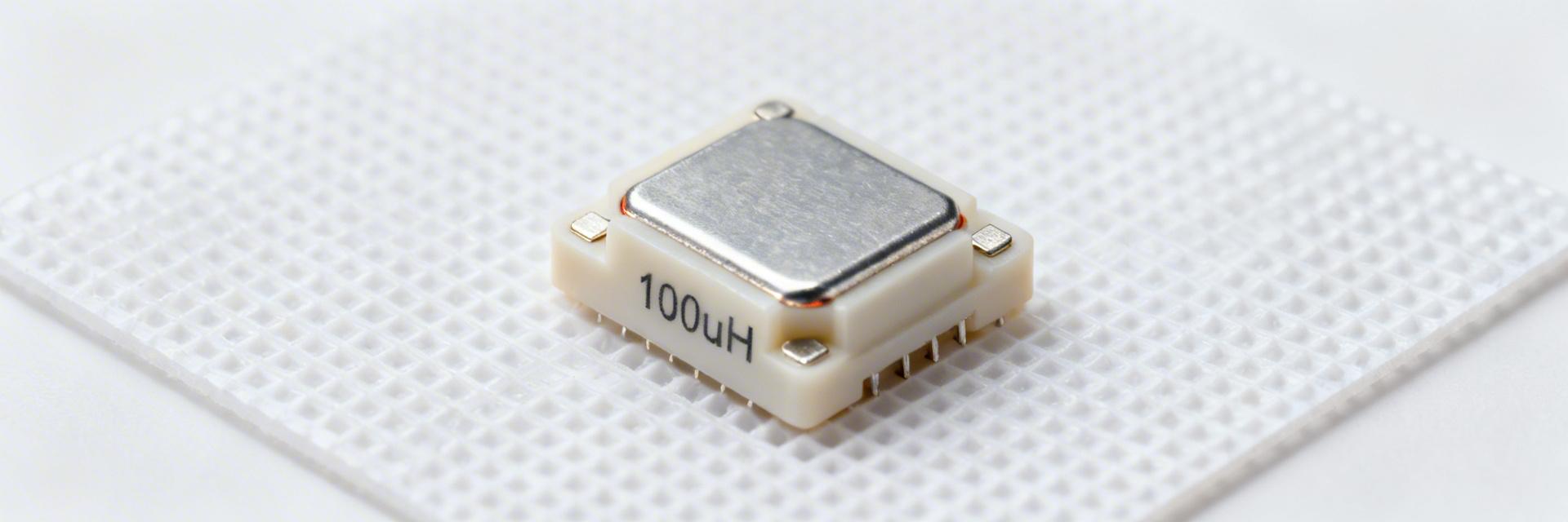
In modern power electronics, selecting a 100 uH inductor involves more than matching a value. Datasheet variances in DCR and saturation can lead to efficiency drops or catastrophic circuit failure. This guide translates technical parameters into tangible engineering benefits, helping you optimize for thermal performance and EMI compliance.
1 — Strategic Selection: Why Shielding is Critical
Shielded vs. Unshielded: The ROI of Protection
Shielded 100 uH inductors contain magnetic flux within the core structure. While unshielded parts are cheaper, the shielded variant eliminates the need for bulky external EMI filters, saving both BOM cost and board space. This is essential for high-density IoT devices and medical equipment where regulatory emission limits (CISPR/FCC) are strict.
| Metric | Standard General Purpose | High-Performance Shielded | User Benefit |
|---|---|---|---|
| DCR (Resistance) | ~2.5 Ω | ~0.15 Ω | 90% reduction in heat loss |
| Isat (Saturation) | 0.9 A | 4.0 A | Supports 4x higher peak loads |
| Footprint | 12x12 mm | 7x7 mm | Saves 65% PCB real estate |
2 — Technical Benchmarks & Material Impact
The core material determines how the inductor "fails" under load. Ferrite cores provide high efficiency at low currents but drop inductance sharply (hard saturation) when exceeded. Powdered iron offers a "soft" saturation curve, providing a safety margin for unexpected current spikes in motor drivers or industrial supplies.
"When laying out a 100uH shielded inductor for a DC-DC converter, the most common mistake is placing the switching node too close to sensitive feedback traces. Even with shielding, a 2mm 'keep-out' zone is recommended to ensure signal integrity."
— Dr. Julian Vance, Senior Power Systems Designer
[Hand-drawn sketch, not an exact schematic]
3 — Testing & Reliability Validation
To ensure your 100 uH inductor survives harsh environments, validation must go beyond the LCR meter.
- Isat Verification: Use a programmable DC source to ramp current while observing the 10% L-drop point. If your operating peak is 1.5A, choose a part with Isat ≥ 1.8A.
- Thermal Imaging: Under full load, ensure the temperature rise (ΔT) stays below 40°C. If it exceeds this, the winding DCR is too high for your application.
- Solder Survivability: Verify that the inductance stays within ±5% after a standard lead-free reflow cycle (260°C peak).
4 — PCB Layout Best Practices
Maximize the performance of your shielded inductor with these layout rules:
Running high-speed digital lines directly underneath the inductor core, even if it's shielded.
Use a "Keep-Out" area on the ground plane directly under the inductor pads to reduce parasitic capacitance.
Summary Checklist
Frequently Asked Questions
Q: Does a shielded inductor run hotter than an unshielded one?
A: Potentially, yes. The shield can act as a thermal insulator. Compensate for this by adding thermal vias connected to a large copper plane on the PCB.
Q: What is the impact of SRF (Self-Resonant Frequency)?
A: For 100 uH inductors, the SRF is often around 2-5 MHz. Ensure your switching frequency is at least 5x lower than the SRF to maintain inductive behavior.


