
A common design bottleneck is choosing and validating the right 4.7µH SMD inductor so the power stage meets ripple, efficiency, and EMI targets without unexpected thermal or saturation failures. This introduction frames a compact selection guide and hands-on test procedures engineers can execute quickly in prototype and production.
The guide focuses on practical metrics—DCR, Isat, Irms, SRF, thermal behavior—and delivers concise test procedures for LCR, DC ramp, thermal soak, and in-circuit validation. It emphasizes measurable margins and reproducible records so suppliers and audit trails align with engineering decisions.
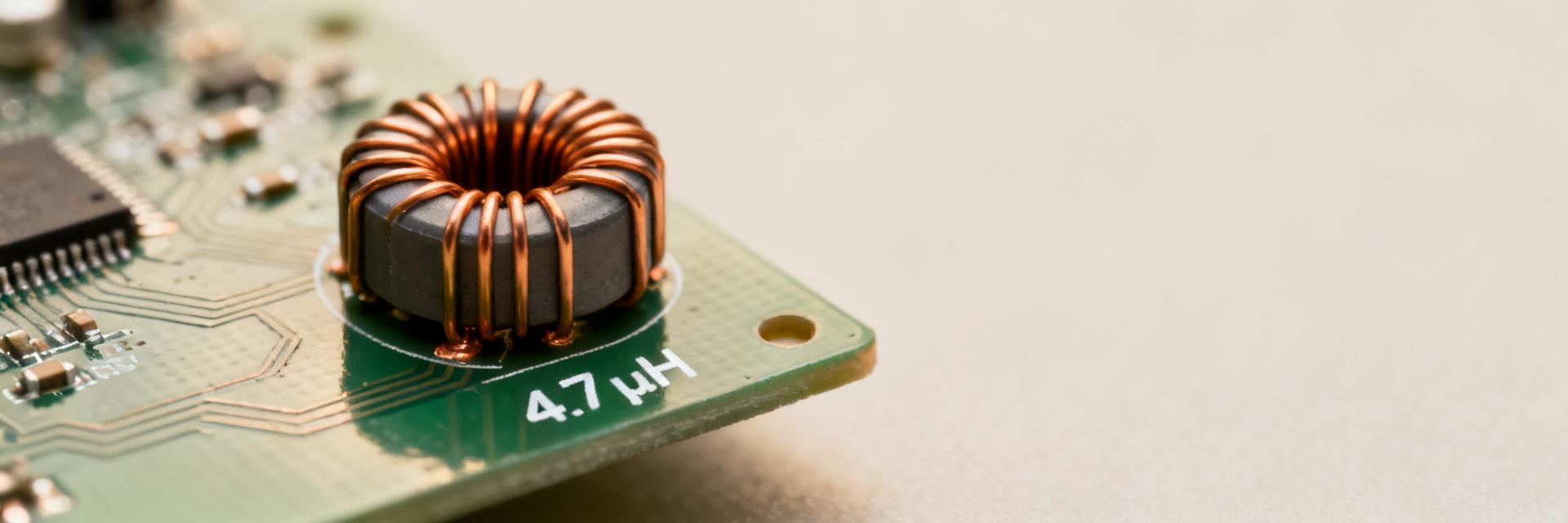
Why designers choose 4.7µH SMD inductors (Background)
Typical applications & performance targets
Point: 4.7µH SMD inductors commonly serve as energy-storage elements in low-to-mid power buck converters and as LC filter inductors in small supplies.
Evidence: designers target switching frequencies from 200kHz to 2MHz with ripple currents typically 20–50% of DC output current.
Explanation: choose L to balance ripple with core size, and prioritize Isat when peak currents spike.
Key electrical and mechanical parameters
Point: Rank L, tolerance, DCR, Isat, Irms, SRF, Q, package height and mounting class.
Evidence: DCR controls copper loss; Isat determines usable current margin; SRF limits high-frequency behavior.
Explanation: for power stages prioritize Isat and DCR; for filtering prioritize SRF and Q; for space-constrained designs pick low-profile shielded parts.
How to read and validate 4.7µH SMD inductor datasheets (Data-analysis)
Interpreting inductance vs. frequency and tolerance specs
Point: Datasheets show inductance measured at a reference frequency; inductance falls with rising frequency approaching SRF.
Evidence: many parts list L at 100kHz or 1MHz plus % tolerance.
Explanation: for switching converters inspect the inductance vs. frequency plot near switching harmonics; use the long-tail query concept “4.7µH SMD inductor inductance vs frequency” to ensure usable L at your Fs.
Understanding DC resistance, saturation graphs, and thermal limits
Point: DCR curves, Isat deflection, and temperature derating govern loss and reliability.
Evidence: Isat often specified at 10–20% inductance drop; DCR increases with temperature per copper TCR.
Explanation: specify Isat margin of 20–50% above peak instantaneous currents and account for DCR rise at operating temperature to avoid efficiency surprises.
Selection guide — matching a 4.7µH SMD inductor to your power stage
| Selection Criteria | Key Formula / Benchmark | Design Target |
|---|---|---|
| Inductance (L) | L = (Vin − Vout)·D / (ΔI·Fs) | ΔI ≈ 20–50% of Iout |
| Saturation Current (Isat) | Isat ≥ Peak_Current × 1.3 | Avoid 10-20% L drop |
| Copper Loss (P) | P = Irms² · DCR | Minimize thermal rise |
Mechanical footprint, mounting, and EMI trade-offs
Point: Package height and shielding affect SRF and radiated emissions. Evidence: shielded parts contain stray fields and reduce board coupling; taller parts often have higher SRF. Explanation: choose shielded SMDs for EMI-sensitive boards, balance height with reflow reliability, and verify recommended land pattern.
PCB layout, soldering & implementation best practices (Method / Implementation)
Minimize switching loop area. Place input cap adjacent to switch, then inductor, then output cap. Use multiple vias for current return and route sensitive traces away from inductor edges.
Solder paste volume and thermal vias impact heating. Follow vendor reflow recommendations and consider thermal vias under adjacent copper areas to spread heat for higher Irms applications.
Bench test walkthrough — step-by-step test procedures for designers
1. LCR and impedance measurement procedure
Point: Characterize L, Q and SRF across a frequency sweep. Evidence: use a calibrated four-terminal LCR meter; measure at 100kHz, 1MHz, and a sweep to SRF. Explanation: record nominal L, tolerance band, Q at Fs, and SRF; log results for each lot.
2. DC & dynamic tests: DCR, saturation, thermal derating
Point: Verify DCR, Isat ramp, and thermal performance. Evidence: measure DCR with a milliohm meter, perform an Isat ramp at ~1A/s until L drops 10%. Explanation: in-circuit validate with oscilloscope; ensure bandwidth ≥50MHz and sampling ≥200MS/s to capture ripple.
Troubleshooting, validation checklist, and production qualification
Common failure modes: Symptoms include excessive ripple, thermal drift, audible noise, and saturation. Evidence: excessive ripple traces to insufficient L; audible noise indicates magnetostriction. Explanation: diagnose with DC ramp, thermal camera, and spectrum analysis.
Summary
- Choose a 4.7µH SMD inductor by balancing ripple needs and Isat/Irms margins; verify DCR impact on losses.
- Follow the selection guide: compute L from ripple targets, select Isat ≥30–50% above peaks.
- Execute test procedures: calibrated LCR sweeps, DC ramp saturation tests, and in-circuit oscilloscope verification.
FAQ
How to test 4.7µH SMD inductor for Isat and DCR?
Use a four-wire milliohm measurement for DCR, then perform an Isat ramp: supply a slowly increasing DC current (≈1A/s) while monitoring inductance; define Isat where inductance falls by ~10%.
What are recommended test procedures for in-circuit ripple measurement?
Probe across the output capacitor using a short ground spring; set oscilloscope bandwidth ≥50MHz and sample rate >200MS/s. Compare to simulated ΔI and datasheet expectations.
How to select 4.7µH SMD inductor for a buck converter application?
Calculate L from allowed ripple, choose Isat above peak switch current plus margin, and verify DCR-driven losses. If EMI is sensitive, select shielded packages.


