
Point: This note distills the key rated values and test conditions from the 784771221 inductor datasheet so engineers can get a fast, reliable reference. Evidence: The part is specified as 220 µH nominal inductance, ~990 mA rated current, ~348 mΩ maximum DCR, with measurements referenced at 100 kHz and an operating range down to −40 °C and up to +125 °C. Explanation: That combination of inductance, current, and DCR sets expectations for losses and thermal behavior in compact SMD power designs.
Point: The goal here is practical utility rather than marketing. Evidence: This write-up summarizes mechanical/environmental limits, complete electrical specs, verification methods, layout guidance, and a procurement/testing checklist. Explanation: Engineers get a single-page technical reference that pairs datasheet numbers with measurement and derating advice for rapid evaluation and prototype validation.
1 — Product Overview & Background
What the 784771221 part number denotes
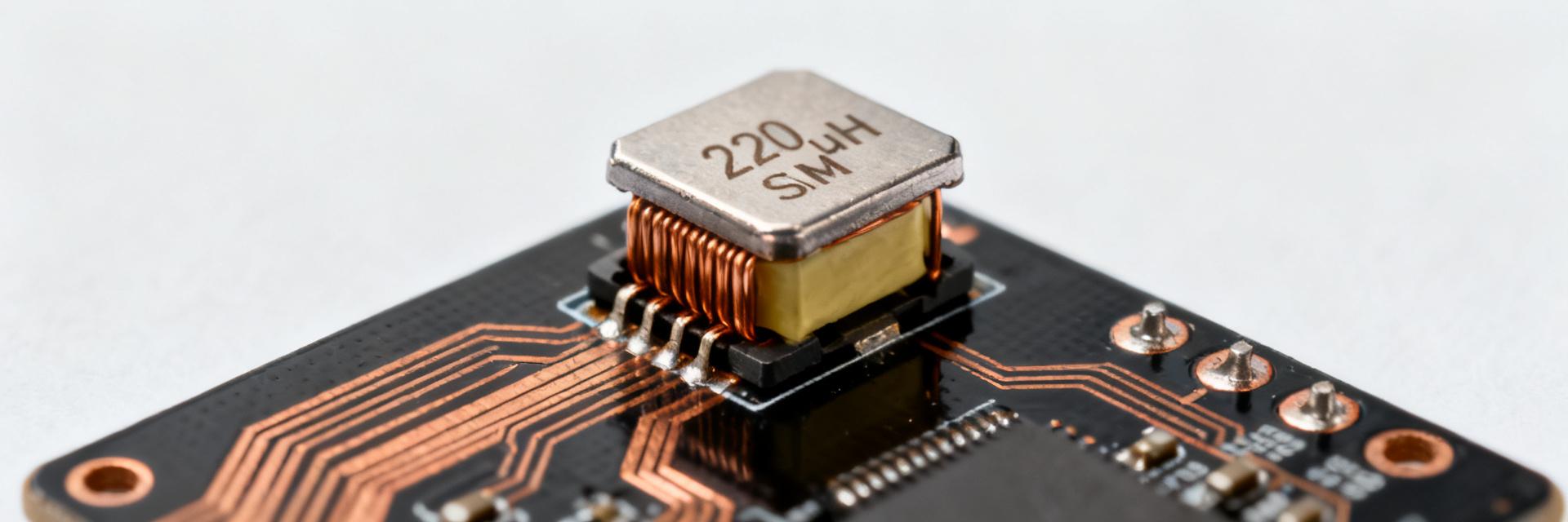
Point: The numeric ID encodes a 220 µH shielded SMD power inductor with a compact rectangular package. Evidence: The datasheet lists nominal inductance 220 µH with a tolerance class and a shielded construction suitable for surface-mount placement; it is described in a dedicated SMT package footprint. Explanation: Nominal values plus shielding indicate the component is aimed at power-rail LC filtering and low-frequency energy storage where EMI containment and board space are important.
Key mechanical and environmental ratings
Point: Mechanical and environmental ratings determine board-level suitability. Evidence: The datasheet specifies an SMD/SMT footprint, recommended soldering profiles for reflow, and an operating temperature span typically from −40 °C to +125 °C, with package dimensions appropriate for 12 mm × 12 mm × 6 mm class power inductors. Explanation: Those ratings guide PCB footprint, solder process acceptance, and selection for automotive or industrial ambient ranges where thermal derating and vibration resistance matter.
2 — Complete Electrical Specs (Data Deep-Dive)
Core electrical parameters
Point: Inductance, tolerance and test conditions are the baseline electrical specs. Evidence: Nominal inductance is 220 µH with a stated tolerance (see datasheet table), and the measurement frequency used for inductance characterization is 100 kHz; Q factor is implied through impedance and measurement conditions. Explanation: Because inductance and Q vary with frequency, using the datasheet’s 100 kHz reference when comparing measured L and inferred losses avoids false mismatches caused by different test setups.
Current-related specs
Point: Current handling and DCR govern loss and thermal performance. Evidence: The datasheet lists rated current around 990 mA and a maximum DCR near 348 mΩ, with a saturation behavior and a higher short-term peak (e.g., 1.1 A indicated for certain transient conditions). Explanation: DCR directly sets I²R losses (approximate power loss ≈ I²·DCR), so at 0.99 A the loss is ~0.34 W, which must be mapped to thermal impedance and PCB cooling to estimate temperature rise; saturation current affects inductance under large ripple.
3 — How to Read, Measure, and Verify
Measurement setup and common test pitfalls
Point: Measurement accuracy depends on fixture, test frequency, and instrument. Evidence: The datasheet’s inductance is referenced at 100 kHz; using an LCR meter set to that frequency and a low-inductance test fixture minimizes error. Explanation: Common pitfalls include fixture inductance skewing low-value measurements, using the wrong frequency (which shifts apparent L and Q), and not accounting for DC bias when measuring inductance under operating current—always document instrument, fixture, and frequency when comparing to datasheet values.
Interpreting ratings: derating and safety margins
Point: Conservative derating avoids thermal or saturation failures in production. Evidence: With DCR ~348 mΩ and rated current ~990 mA, I²R loss at rated current is appreciable; designers typically derate continuous current by 20–30% to limit thermal rise. Explanation: Use rule-of-thumb power loss ≈ I²·DCR for steady-state heating, apply margin for ripple-induced additional loss, and factor tolerance stack-ups when sizing LC corner frequencies in filters to ensure behavior across component spreads.
4 — Typical Applications & Layout Recommendations
Point: The part suits several low-frequency power roles. Evidence: 220 µH with ~1 A current capability is appropriate for small buck converters, LC post-filters on power rails, and EMI suppression on low-speed rails where magnetics provide filtering rather than high-frequency energy transfer. Explanation: Choose this inductance where energy storage and low ripple are priorities; confirm saturation current versus peak ripple current and consider alternative values for higher switching frequencies.
PCB layout, grounding, and placement best practices
Point: Layout strongly affects measured performance and losses. Evidence: Datasheet package guidelines imply tight placement to minimize loop area; thermal vias and copper pour under/around the part will reduce temperature rise from I²R losses. Explanation: Keep the inductor close to switching nodes, minimize trace length to input/output caps, avoid routing sensitive analog lines across the magnetics loop, and use thermal relief only where allowed by mechanical reliability requirements.
5 — Procurement & Quick Implementation Guide
Point: Confirming datasheet revision and mechanical compatibility prevents late surprises. Evidence: Verify the part number, revision code, inductance, rated current, DCR, operating temperature, and packaging format (tape & reel) before purchase; watch for listings that omit revision or specify inconsistent specs. Explanation: A short procurement checklist reduces risk: confirm electrical specs, confirm footprint dimensions against your PCB, and request sample units for bench verification under expected ripple and ambient conditions.
Validation Steps for Prototypes
Point: A compact validation flow accelerates go/no-go decisions. Evidence: Typical steps: order evaluation samples, verify dimensions on the board, measure inductance at 100 kHz, measure DCR with a Kelvin ohm test, then run a thermal test under worst-case ripple and continuous current. Explanation: Pass criteria include inductance within tolerance at test frequency, DCR below specified max, temperature rise within allowed margin, and no unacceptable saturation under peak ripple—document results and update BOM status accordingly.
Summary
Point: Verify inductance, DCR, and current capability under datasheet test conditions before committing to production. Evidence: The 784771221 inductor datasheet specifies 220 µH nominal, ~990 mA rated current, ~348 mΩ max DCR, tested at 100 kHz, with −40 °C to +125 °C operating range. Explanation: Those electrical specs drive loss calculations, thermal design, and derating rules; use the measurements and checklist above to validate suitability for your power-rail or filter application.
- Confirm 220 µH at 100 kHz and tolerance when measuring L to match the 784771221 inductor datasheet reference conditions.
- Calculate steady-state loss using I²·DCR (~0.34 W at 0.99 A) and verify thermal management with PCB copper and vias.
- Derate continuous current by ~20–30% for margin against thermal rise and ripple-induced loss; check saturation at expected peak currents.
- Follow footprint and reflow recommendations to preserve mechanical reliability and measured electrical performance.
FAQ
What are the critical checks for 784771221 before PCB assembly?
Point: Focus on dimensions and electrical conformity. Evidence: Verify footprint dimensions against the datasheet mechanical drawing, confirm inductance and DCR on received samples at the datasheet’s test frequency, and ensure packaging (tape & reel) and temperature rating meet your process. Explanation: These checks prevent misplacement, rework, and unexpected thermal issues during reflow and operation.
How should I test DCR and thermal rise for 784771221 in a prototype?
Point: Use Kelvin resistance and powered thermal profiling. Evidence: Measure DCR with a four-wire ohmmeter at room temperature, then power the part at expected DC plus ripple currents and monitor temperature with a thermocouple or IR camera until steady state. Explanation: Compare measured DCR and temperature rise to calculated I²·DCR losses and ensure thermal margins are acceptable for continuous operation.
What derating rule is recommended for 784771221 in continuous applications?
Point: Apply conservative current derating to protect against heating and saturation. Evidence: With a rated current near 990 mA and measurable I²R losses, a 20–30% derating for continuous duty is a practical starting point, increased if ambient is high or airflow is limited. Explanation: Derating reduces long-term stress, limits thermal cycling, and keeps inductance out of the knee region caused by partial saturation under ripple peaks.


