Introduction (data-driven hook)
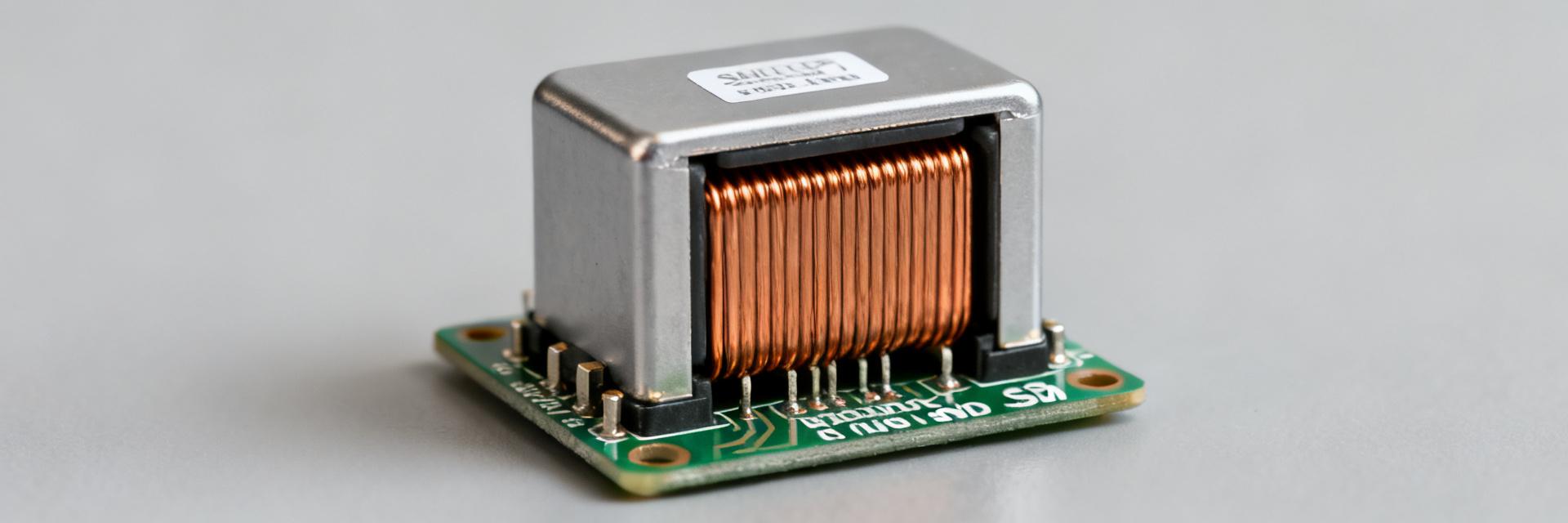
Point: The 784770471 inductor is specified as a 470 µH, shielded SMD power inductor with a rated continuous current near 0.8 A and a typical DC resistance about 0.57 Ω.
Evidence: These headline numbers define its behavior in low-frequency filters and low‑power buck converters.
Explanation: This article walks through the datasheet, highlights the numeric limits that drive design decisions, provides verification steps, and ends with a compact engineer’s checklist for confident selection.
1 — Product overview & key identifiers (background)
What the part number means
Point: The model code groups this part in a shielded SMD power-inductor family with a drum-style core and AEC‑Q200 screening hints in some catalogs.
Evidence: The datasheet section titled "Ordering information / Part family" lists family, footprint, and package style; those fields map the numeric code to inductance and packaging variants.
Explanation: Read the datasheet's ordering table to confirm footprint, material code, and any suffixes that indicate tighter tolerance or special screening before placing on a BOM.
Quick spec snapshot (at-a-glance table)
Point: Engineers need headline specs at a glance to assess fit for purpose.
| Parameter | Typical / Spec |
|---|---|
| Inductance | 470 µH |
| Rated DC current (continuous) | ~0.8 A |
| DC resistance (typical) | ~0.57 Ω |
| Package | SMD, shielded |
| Operating temp | typ. −40 to +125 °C |
| Typical height / footprint | low-profile SMD drum |
Explanation: Use this TL;DR when comparing candidate inductors; verify the mechanical drawing and land pattern in the full datasheet before layout.
2 — Electrical specifications explained (data analysis)
Inductance tolerance & frequency behavior
Inductance tolerance and frequency response determine whether the part meets filter impedance and converter ripple requirements. The datasheet provides inductance tolerance (±X%), impedance vs. frequency curve including self-resonant frequency, and an inductance-vs-current plot showing saturation behavior.
Design Insight: For low-frequency filters, ensure inductance at operating current stays within tolerance; saturation margin is critical where the slope flattens.
DC resistance (DCR) and thermal impacts
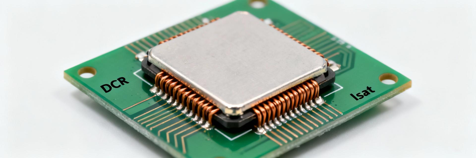
DCR controls I²R losses and heating. Use P = I²·R with the rated current to quantify power loss; e.g., at 0.8 A and 0.57 Ω, P ≈ 0.365 W.
Design Insight: Dissipation produces temperature rise; check the temperature-rise vs. current plot. If unavailable, assume conservative derating.
3 — Current limits, derating & thermal constraints
Rated current vs. Saturation current vs. Thermal current
Design should use the lowest of these limits for safety margin—often derate continuous current to 60–80% of the saturation or thermal limit depending on duty cycle and ambient.
Operating temperature range and maximum part temperature
Specified range: −40 to +125 °C. Keep copper pours for heat sinking, avoid placing heat sources adjacent to the inductor, and verify worst-case junction temp.
4 — How to read and verify the datasheet
Essential plots and tables to check:
- Impedance vs. Frequency
- Inductance vs. DC bias (current)
- Temperature-rise vs. current
- Mechanical drawings & Land patterns
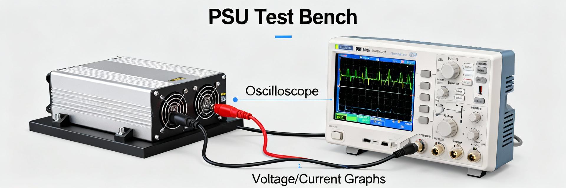
Lab verification checklist:
5 — Design examples & application notes
Typical use cases: Power filters, low-frequency buck converters for low-power rails, and EMI suppression. High inductance (470 µH) favors LF filters over high-current switching stages.
Quick design example: 5 V → 3.3 V buck at 100 mA (200 kHz). L=470 µH gives very small ripple current (ΔI). I²R loss at 0.1 A is P≈0.01·0.57≈0.0057 W (negligible).
6 — Practical limits & Final Checklist
Final engineering checklist before release
- ✓ Verify inductance at target frequency and DC bias.
- ✓ Confirm DCR and calculate I²R loss at worst-case current.
- ✓ Validate thermal rise at worst-case ambient.
- ✓ Confirm footprint, height, and reflow profile compatibility.
- ✓ Apply derating margin for saturation and thermal limits.
FAQ (common questions)
How to test this inductor in the lab?
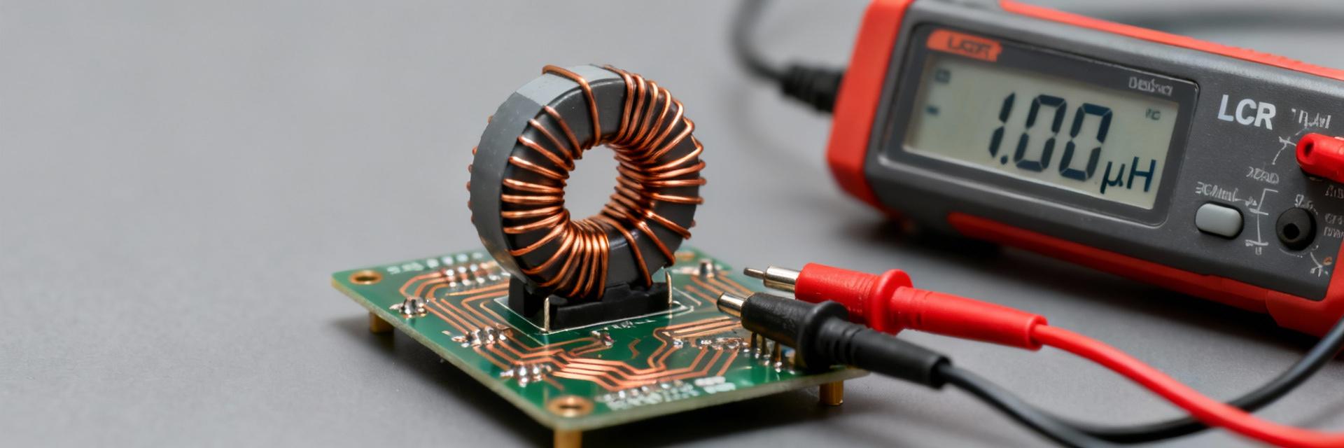
Measure inductance with an LCR meter at specified frequency; measure DCR with a four-wire meter; perform a thermal-rise test by passing rated current and monitoring with a thermocouple.
What is the DCR impact on design?
DCR determines copper losses and heating. Calculate P = I²·R. If power loss is significant, consider a part with lower DCR or improve PCB thermal coupling.
How to check saturation current for an application?
Find the L-vs-I curve and identify Isat. Ensure peak in-circuit currents remain below the derated saturation value (typically 60–80% margin).
SEO Keywords: 784770471 inductor, datasheet, specs, power inductor, SMD shielded