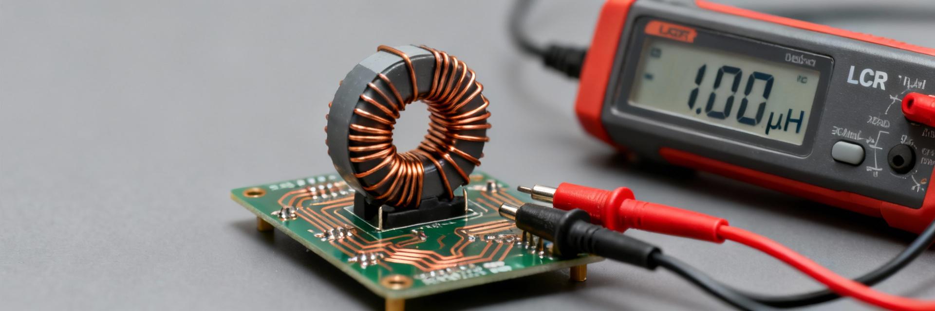
The 78477620 is specified as a 100 µH wirewound drum-core inductor with ±20% tolerance, a rated current around 1.02 A and a maximum DC resistance near 350 mΩ. This distillation pulls datasheet essentials into a single reference to accelerate BOM checks, PCB footprint verification, and thermal derating decisions.
1 — Product overview & physical description
The 78477620 is an unshielded drum-core choke designed for cost-effective EMI and power filtering. Its construction combines a ferrite drum core with enamelled copper winding, offering robust mechanical support and predictable inductance at the expense of higher external stray fields compared to shielded alternatives.
1.1 — Component type & construction
As a wirewound component, the 78477620 uses discrete turns of copper wire. This topology ensures stable inductance at low frequencies and moderate saturation performance. It is particularly applicable where space and cost efficiency outweigh the need for absolute EMI containment.
2 — Electrical specifications at a glance
Core electrical ratings determine application fit. The following metrics represent the headline performance envelope for the 78477620.
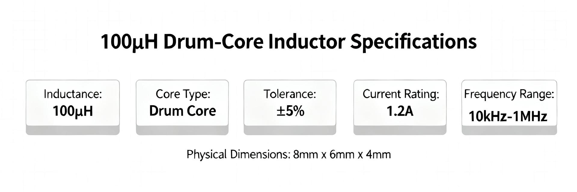
| Parameter | Value | Test Condition / Note |
|---|---|---|
| Inductance | 100 µH | ±20% at reference frequency |
| Tolerance | ±20% | Standard for drum-core series |
| Rated Current | ≈1.02 A | Thermal limit (ΔT rise) |
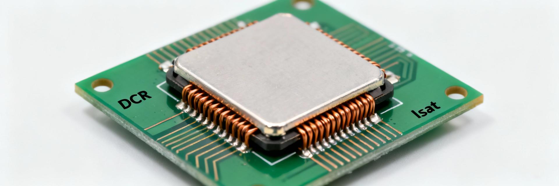
| DC Resistance (DCR) | Max ~350 mΩ | Measured at 20°C ambient |
| Core Type | Ferrite | Unshielded Drum Core |
3 — Performance metrics & test conditions
Measurement methods significantly impact declared values. Inductance is typically validated using an LCR meter at 100 kHz. In-circuit measurements may differ due to parasitic coupling; always replicate manufacturer test conditions during validation.
3.1 — Thermal & derating behavior
Apply a derating factor of 20–50% for continuous operation in high-temperature environments. While the saturation current often sits above the rated current, temperature-induced DCR increases must be factored into the total thermal budget of the PCB.
4 — Typical applications & selection
This class of inductor is commonly found in input/output filtering for sensor modules, MCU power rails, and low-power DC-DC converters where current remains below the 1A threshold.
5 — How to verify & integrate
PCB layout is critical for unshielded chokes. Place the 78477620 close to decoupling capacitors and use wide, short traces to minimize loop area. Avoid routing high-speed signal traces directly beneath or parallel to the component to mitigate EMI coupling.
6 — Quick spec checklist
- Inductance: 100 µH ±20% — Confirm at specified frequency.
- Rated current: ≈1.02 A — Apply 20-50% derating for safety.
- DCR: < 350 mΩ — Verify at 20°C to manage voltage drop.
- Footprint: Check lead spacing and component height.
Summary
- Core metrics: 100 µH, 1.02 A, 350 mΩ DCR.
- Design rule: Use for low-frequency filtering; prioritize spacing to reduce EMI.
- Validation: Measure samples under thermal load before mass production.
Frequently Asked Questions
What test conditions should be used to validate the inductance in the datasheet?
Use an LCR meter at the datasheet reference frequency and temperature (commonly 1 kHz or 100 kHz, 20°C). Measure with short leads or Kelvin fixtures to avoid added series resistance; document your test method to compare against the datasheet.
How much current derating is recommended for continuous operation?
Apply a conservative derating of 20–50% depending on enclosure temperature and duty cycle. For continuous duty in warm environments, favor the higher derating to avoid saturation and excessive heating.
What should be checked on a sample before PCB approval?
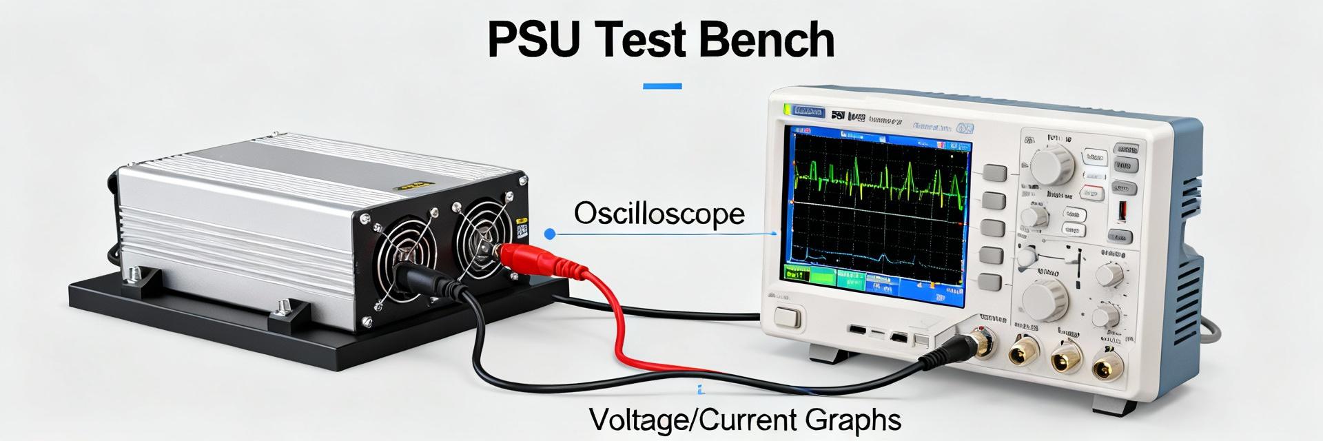
Measure DCR and inductance, perform thermal soak and impedance sweeps, inspect after reflow for mechanical damage, and validate in-circuit ripple and temperature rise under expected load conditions.
Why is component placement critical for the 78477620 inductor?
Due to its unshielded drum-core topology, it has higher external stray fields. Designers should avoid placing it near sensitive signal traces or high-gain amplifiers to prevent unintended EMI coupling and noise injection.