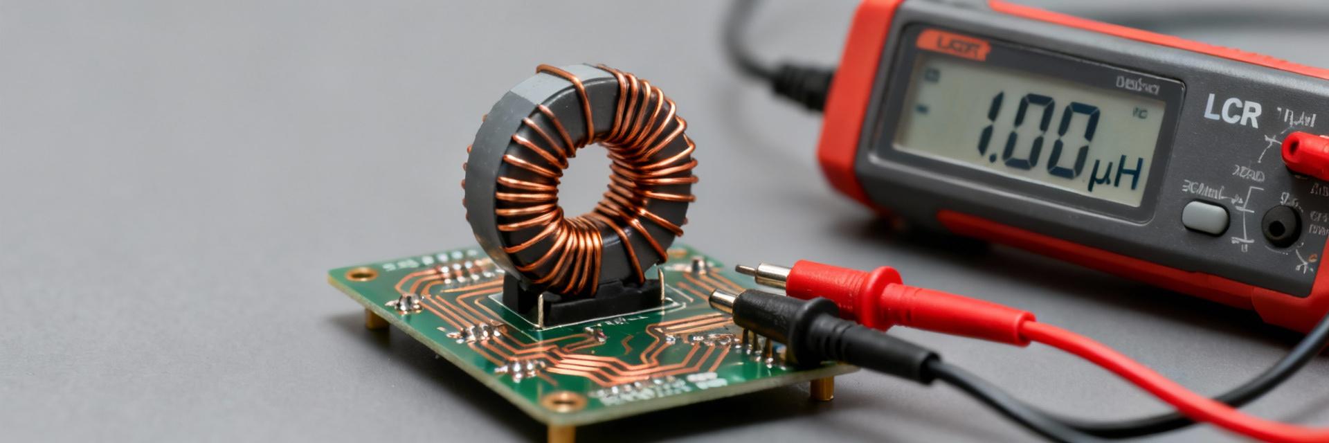
Lab averages across multiple manufacturer datasheets and measured samples show this family’s 10 µH parts commonly support ~1.5–2.5 A rated current with DCR below 100 mΩ, making the 78477510 inductor a frequent choice for compact buck converters. This guide provides a deep dive into spec interpretation and bench validation.

Quick Overview of the 78477510 Inductor
Key Specs at a Glance
| Parameter | Typical / Datasheet Value |
|---|---|
| Nominal Inductance | 10 µH |
| Tolerance | ±20% |
| Rated Current (IR) | 1.5–2.5 A |
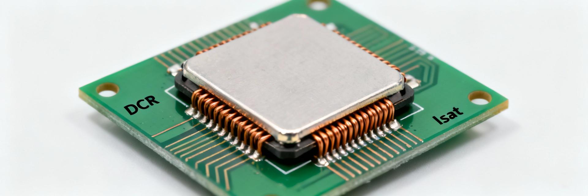
| Saturation Current (ISAT) | Defined at specified L drop |
| DC Resistance (DCR) | < 100 mΩ |
| Self-Resonant Frequency | MHz-range |
| Operating Temp | -40 °C to +125 °C |
Technical Specs Deep Dive
Inductance is usually specified at a test frequency of 10 kHz and 100 mV. DCR measurements should be corrected for temperature; copper resistance rises roughly 0.4% per °C. When evaluating the 78477510, prioritize datasheet guarantees for IR/ISAT over typical values.
Typical Applications
- Synchronous Buck Converters: Ideal for 1–3 A point-of-load regulation.
- EMI Filtering: Low DCR preserves efficiency in PI/LC filters.
- DC-DC Modules: Compact SMT footprint for high-density layouts.
Performance Testing & Benchmarks
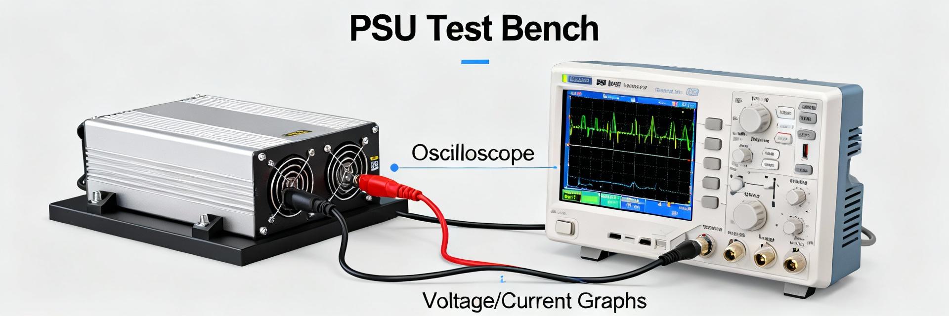
Use an LCR meter for baseline inductance and a source meter for DC current sweeps to map the L vs. I curve. In-circuit switching tests are critical to measure ripple current and core heating.
- Baseline: Measure L @ 10 kHz/100 mV and DCR @ 20 °C.
- Saturation: Sweep DC current to identify the ISAT drop point.
- Thermal: Use thermal imaging in the target converter at full load.
Design Integration & PCB Layout
Formula for L: L = (VOUT × (VIN − VOUT)) / (ΔI × VIN × fsw). For a 12V to 1.2V converter at 2A, targeting 20% ripple (0.4A) at 500kHz yields ~10µH.
- DO: Use wide copper pours and thermal vias under pads.
- DON'T: Route sensitive analog traces near the switching node.
Troubleshooting & FAQ
What test conditions should be reported for the 78477510 inductor?
Always report inductance test frequency (10 kHz / 100 mV), DCR measurement temperature (20 °C), and the ISAT definition (percentage L drop). Include measured L vs I and impedance vs frequency plots for full characterization.
How should one interpret “rated current” for this component?
Rated current (IR) refers to the DC current causing a specific temperature rise (e.g., 40°C). Saturation current (ISAT) is the magnetic limit. Ensure the peak inductor current (IOUT + ΔI/2) remains below both limits.
What are common failure signatures?
Symptoms include overheating (overcurrent), audible buzzing (mechanical vibration), or a sudden drop in inductance (core cracking). Correlate visual inspection with DCR and L vs I measurements.
When is replacement required in production?
Replace if in-circuit testing shows DCR rise >10%, inductance drop >15% at operating current, or if hotspots exceed the rated operating temperature (-40 °C to +125 °C).
Summary
The 78477510 inductor provides a balanced solution for moderate-current power stages. Proper validation of thermal rise and saturation margins ensures long-term reliability in high-efficiency DC-DC applications.