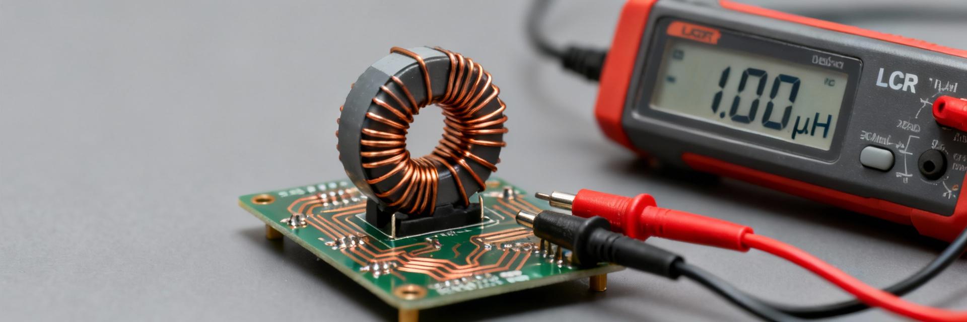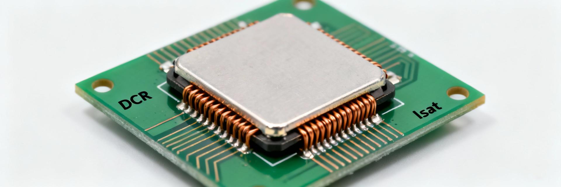
The 78477420 datasheet specifies a nominal inductance of 10 µH, a low DC resistance (DCR) of 12 mΩ, and a rated current of 6.0 A. Designed for buck converters and point-of-load regulators, this component requires careful balance between thermal management and magnetic saturation. This guide translates raw datasheet parameters into practical layout and design strategies.
1 — Core Specifications & Product Snapshot
For immediate design comparison, the table below summarizes the essential electrical and physical constraints of the 78477420.
| Parameter | Typical / Test Condition |
|---|---|
| Inductance (L) | 10 µH @ 10 kHz, 100 mV |
| Tolerance | ±20% |
| DC Resistance (DCR) | ~12 mΩ (Typ) |
| Rated Current (IR) | 6.0 A (ΔT = 40 K) |
| Saturation Current (Isat) | ≥ 12 A (ΔL drop) |
| Package Type | Shielded SMD Power Inductor |
2 — Electrical Performance: L, DCR, and Efficiency
2.1: Small-Signal vs. Large-Signal Inductance
Inductance is characterized at 10 kHz/100 mV. However, real-world switching frequencies (typically 100 kHz to 1 MHz) and DC bias will cause the effective inductance to shift. Designers must validate the L value under their specific ripple current to prevent unexpected regulator instability.
2.2: DCR and Power Loss Budgeting
Conduction loss is calculated as P = I²R. At a 5A load, the 12 mΩ DCR generates 0.3W of heat. Note that DCR has a positive temperature coefficient; as the part heats up, losses increase, potentially leading to thermal runaway if the PCB copper area is insufficient.
3 — Rated Current vs. Saturation Guidelines
3.1: Thermal Rated Current (IR)
The 6.0A rating is a thermal limit defined by a 40K temperature rise above ambient. This is not a hard cutoff but a design envelope. In high-ambient environments (e.g., >60°C), the IR must be derated to ensure the component does not exceed its maximum operating temperature.
3.2: Saturation Current (Isat)
With an Isat of 12A, this part provides significant headroom for peak current events. Ensure the peak inductor current (IDC + ΔIL/2) never exceeds Isat during transient loads or startup to prevent the inductance from collapsing and damaging the switching controller.
4 — Footprint and PCB Layout Implementation
A precision land pattern is critical for both mechanical reliability and thermal dissipation. The 78477420 requires two primary pads with a gap of 4–6 mm. To optimize performance:
- Thermal Vias: Place multiple vias within or near the pads to transfer heat to internal planes.
- Copper Weight: Use at least 2oz copper for high-current paths to minimize trace DCR.
- Solder Fillets: Ensure the stencil aperture allows for a visible fillet on the side of the termination for inspection.
5 — Design Checklist
Pre-Layout Verification
Confirm the DC bias effect on inductance at your maximum load. Verify that the 6.0A rating is adjusted for your specific enclosure's ambient temperature. Ensure the footprint matches the datasheet's mechanical tolerances.
Thermal and Loss Analysis
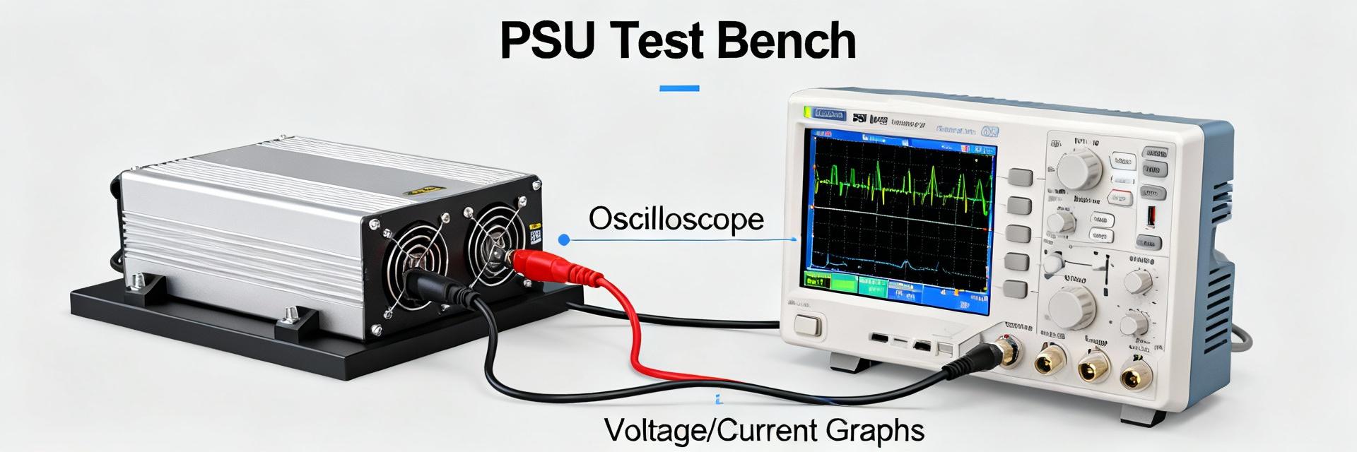
Calculate I²R losses using the maximum DCR. Perform a thermal simulation or use a test board to verify the ΔT does not exceed 40K under worst-case continuous load.
Saturation Margin Check
Ensure that peak switch current limits are set below the 12A Isat value. This prevents core saturation during inductor current spikes or output short-circuit conditions.
Manufacturing & Assembly
Check the reflow profile against the solder paste vendor's spec. Symmetrical pad design is essential to prevent component shifting or tombstoning during the liquidus phase.
Summary
The 78477420 is a robust power inductor offering 10 µH at 12 mΩ. Successful integration requires treating the 6.0A IR as a thermal guideline and the 12A Isat as a hard safety limit. By following the recommended footprint and implementing aggressive thermal management on the PCB, designers can ensure stable and efficient power delivery in demanding industrial applications.