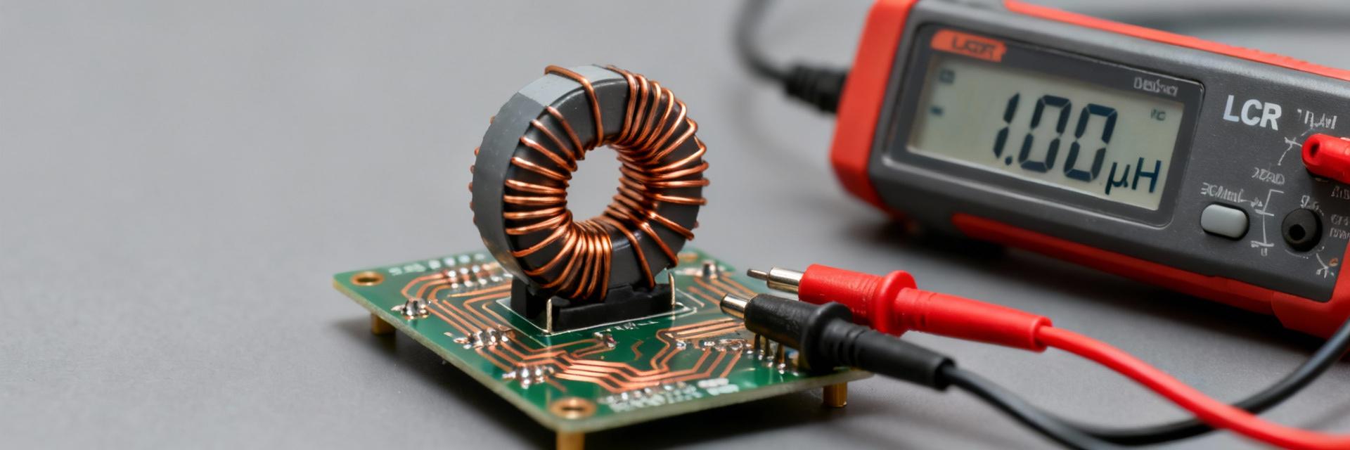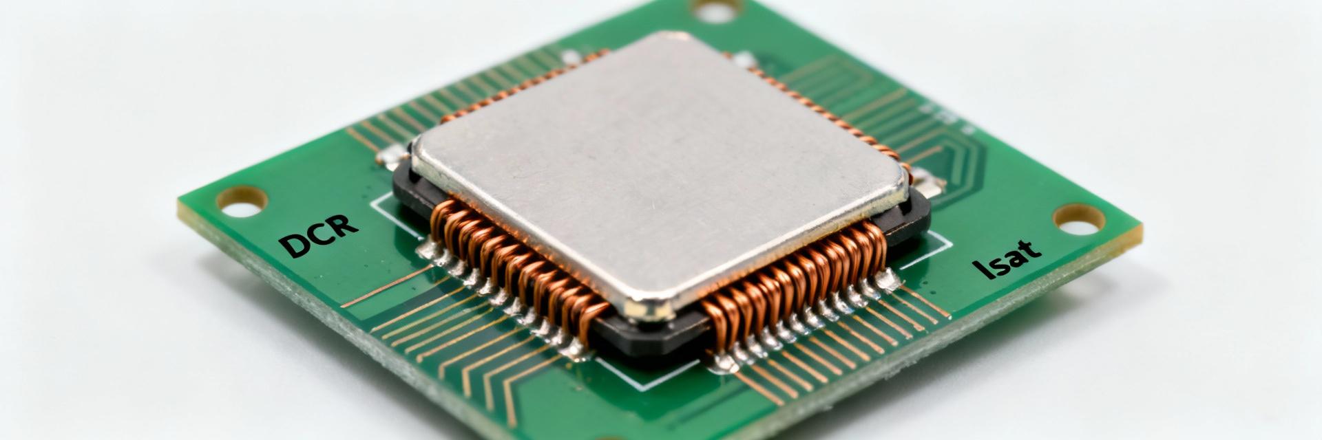
The 78477310 datasheet presents a compact fixed inductor rated near 10 µH, a typical rated current around 1.45 A, and a DC resistance on the order of 182 mΩ. These headline numbers allow engineers to quickly evaluate power loss, saturation margin, and suitability for power-filtering or EMI suppression roles. This summary translates raw technical specs into practical selection and validation guidance for industrial design.
(1) Product Overview & Intended Uses
Form Factor and Electrical Class
POINT The 78477310 is a fixed inductor in a surface-mount package optimized for PCB power rails. Designers must confirm PCB pad geometry and reflow constraints to ensure mechanical reliability and thermal coupling for heat dissipation.
Typical Application Domains
POINT Common uses include output filtering for DC–DC converters and EMI suppression. The 10 µH value balances ripple reduction with physical size, offering a compromise between DCR efficiency and saturation margin.
(2) Key Electrical Specs Analysis
| Parameter | Nominal Value | Condition |
|---|---|---|
| Inductance | 10 µH ±20% | @ 100 kHz, 0.1V |
| Rated Current (IR) | ~1.45 A | ΔT = 40K Rise |
| Saturation Current (Isat) | Typical ~1.7 A | |ΔL/L| < 10% |
| DC Resistance (DCR) | 182 mΩ | Max @ 20°C |
(3) Thermal and Reliability Performance
Maximum operating temperature and derating curves in the 78477310 datasheet dictate allowable continuous current. Since I²R loss yields significant thermal rise, designers should size RMS current relative to the 40K temperature rise limit. Short pulse loads may exceed rated current, provided the thermal time constant is not breached.
(4) Evaluation Guide for Design Integration
To verify suitability, apply the following calculation checklist:
- Power Loss: Ploss = Irms² × DCR.
- Voltage Drop: Vdrop = Idc × DCR.
- Ripple Current: ΔI ≈ Vout / (L × fsw).
(5) FAQ: Engineering Design & Troubleshooting
What is the primary use for the 78477310 inductor?
It is primarily used for output filtering in DC-DC converters (Buck/Boost), EMI suppression, and general-purpose power rail decoupling where space and 1.45A capacity are required.
How does DC bias affect its performance?
Inductance values will drop as DC current increases. Engineers should consult the L vs. Current plots in the 78477310 datasheet to ensure sufficient saturation margin under peak load conditions.
What are the thermal considerations for 1.45A operation?
Operating at 1.45A generates I²R losses based on the 182mΩ DCR. Achieving the rated performance requires proper PCB copper thickness for heat dissipation and derating for high ambient temperatures.
What should I check when replacing this component?
Ensure the replacement matches the 10µH inductance, saturation current (Isat), DCR, and the specific SMD footprint to maintain converter stability and efficiency.
Summary
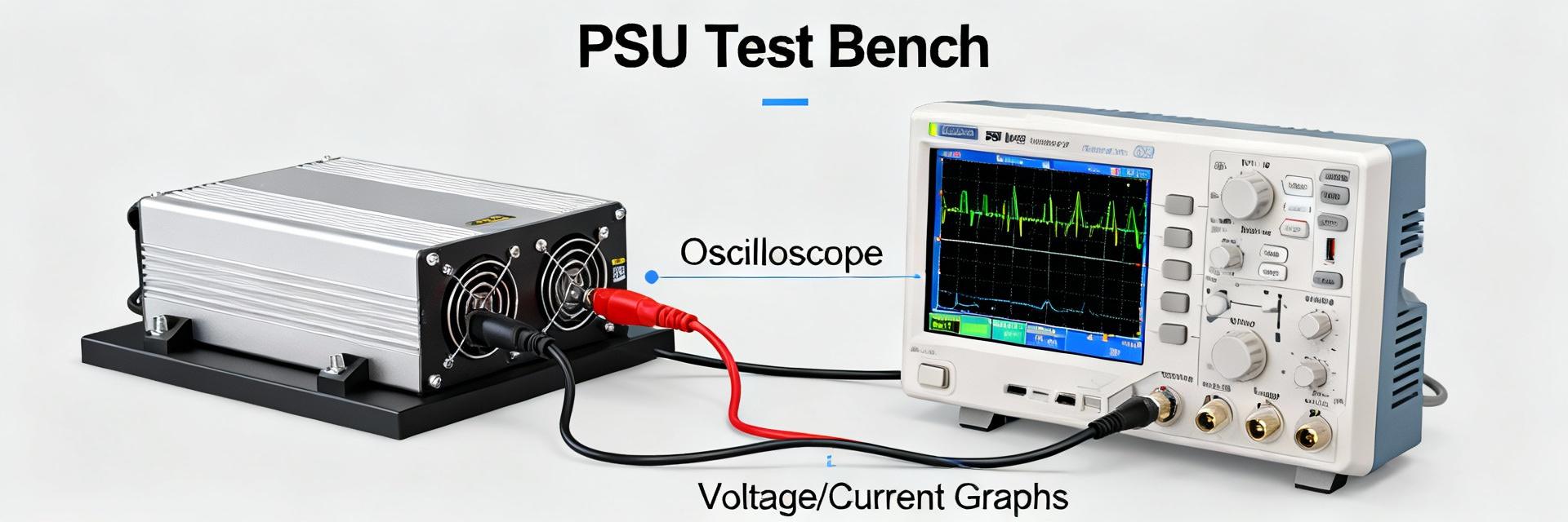
The 78477310 is a versatile 10 µH power inductor tailored for mid-range current applications (~1.45 A). Key selection factors include verifying the 182 mΩ DCR impact on efficiency and monitoring saturation levels via datasheet curves. For robust designs, always perform bench validation to measure impedance sweeps and in-circuit thermal rise under peak operating loads.