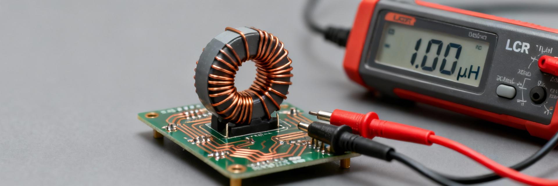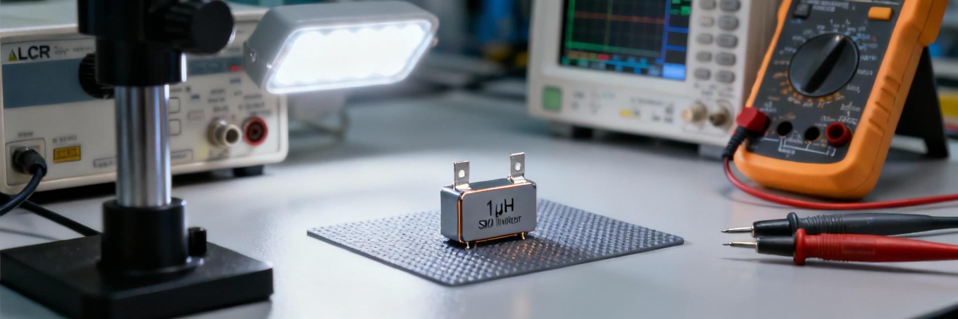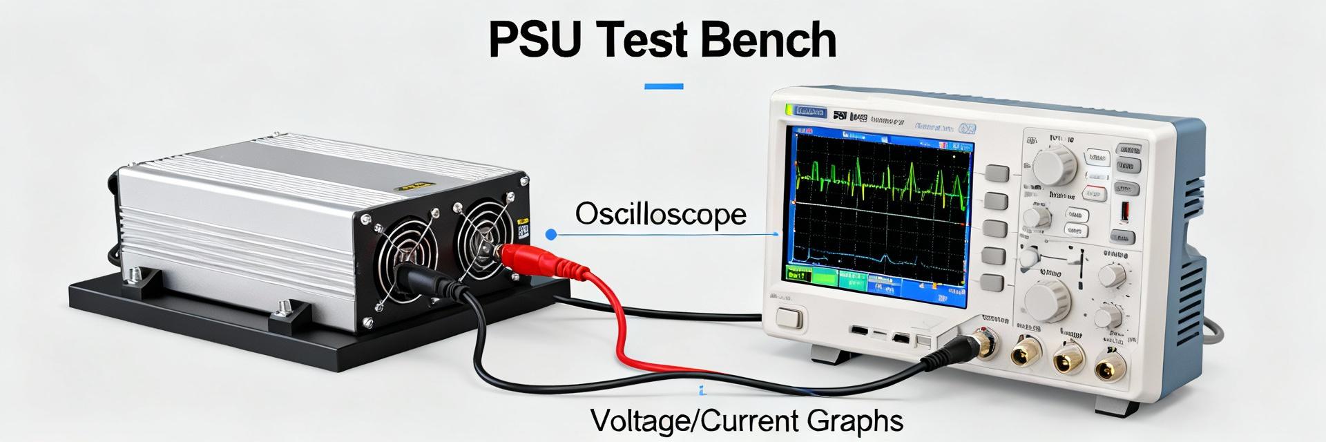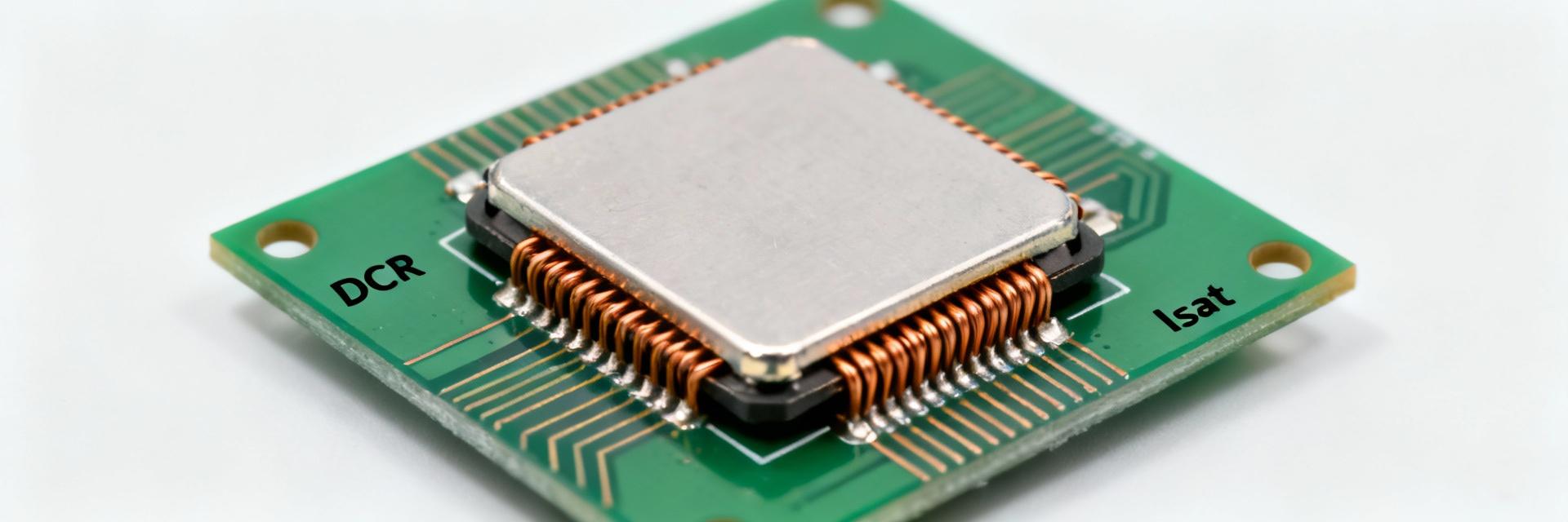
The 78477068 power inductor is a primary choice for mid-power SMD buck converters, featuring a 6.8 µH nominal value and robust multi-amp current handling. This guide provides technical depth for extracting critical specifications from the datasheet, interpreting saturation curves, and ensuring electrical margins for PCB integration.
Product Overview & Key Identifiers
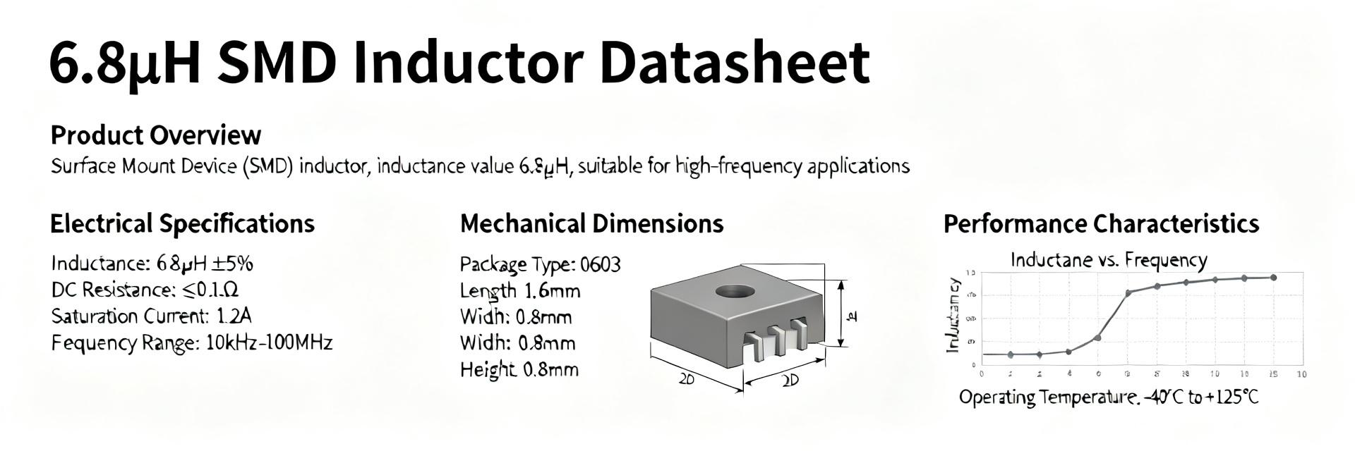
Initial verification requires checking the nominal inductance and package code. The 78477068 series utilizes a 4747 (1212 metric) footprint. Shielded variants are typically preferred to minimize Electromagnetic Interference (EMI) while maintaining low Direct Current Resistance (DCR).
Part Number Meaning & Package ID
Interpret the part number structure: series code, nominal value, tolerance (±20%), and packaging type. Engineers should verify the shielded designation on mechanical drawings to ensure the external magnetic field is contained, which is critical for high-density power layouts.
Electrical Specs & Ratings Deep-Dive
| Parameter | Typical Value / Note |
|---|---|
| Nominal Inductance | 6.8 µH (±20%) |
| DCR (DC Resistance) | Low mΩ range (Refer to specific package table) |
| I_rms (Thermal Current) | Multi-amp rating (Based on 40K temp rise) |
| I_sat (Saturation Current) | Current where L drops 10-30% |
| Package Footprint | 4747 / 1212 metric variant |
| Operating Temperature | -40 °C to +125 °C (Including self-heating) |
Inductance & Frequency Response
While nominal inductance is 6.8 µH, actual performance depends on the test frequency (usually 100 kHz). At higher switching frequencies (MHz range), parasitic capacitance affects impedance. Review the Self-Resonant Frequency (SRF) to ensure the converter operates well below this point.
Current Handling: Isat vs. Irms
Distinguish between magnetic saturation (I_sat) and thermal limits (I_rms). I_sat defines the point where the core can no longer support increased flux, leading to a sharp drop in inductance. I_rms is the continuous DC current that results in a specific temperature rise (typically ΔT=40°C).
Thermal & Reliability Considerations
Thermal management is vital for longevity. Max operating temperatures often reach 125 °C, but engineers must account for ambient temperature and heat dissipation through PCB copper planes. Soldering profiles should follow J-STD-020 standards to prevent internal stress.
How to Verify Datasheet Measurements
Validation on the bench is recommended using a Kelvin connection for DCR measurement to eliminate lead resistance errors. For inductance under bias, an LCR meter with a DC bias source is required to map the real-world L vs. I curve.
Selection Checklist & Best Practices
- Ripple Current: Ensure ΔI is within 20-40% of the output current.
- Peak Current: Maintain peak current at least 30% below I_sat.
- Thermal Margin: Check I_rms against the expected ambient and board temperature.
- Footprint: Verify land patterns to avoid solder bridges or insufficient fillets.
Frequently Asked Questions
How is inductance affected by DC bias?
Inductance typically decreases as DC bias increases; the datasheet L vs I curve shows this trend. Use the curve to determine the DC current where inductance drops by the manufacturer’s specified amount and ensure that expected peak currents remain below that region.
How to check saturation current on the bench?
Measure L under increasing DC bias using an LCR meter with a bias source or a fixture that superimposes DC. Record L decline and note the current at which L falls to the datasheet’s saturation threshold; compare measured value to expected peak currents with margin.
What thermal checks are recommended for board-level reliability?
Estimate power loss = I_rms^2 × DCR and use thermal derating curves to find permitted continuous current at target ambient. Validate with a thermal camera or thermocouples on the assembled PCB under expected load to confirm junction and ambient rise.