As switching frequencies climb and board area tightens, designers are choosing compact SMD power inductors more often — typical board-level power stages now require inductors that balance low DCR, high saturation current and small footprint. This guide explains how to read datasheets, select parts for a 4.7µH requirement, calculate margins, and validate performance on the bench.
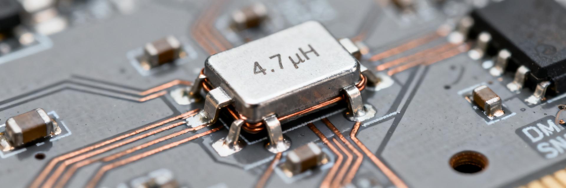
1 — What a 4.7µH SMD power inductor is and why it's used
1.1 — Basic construction & materials
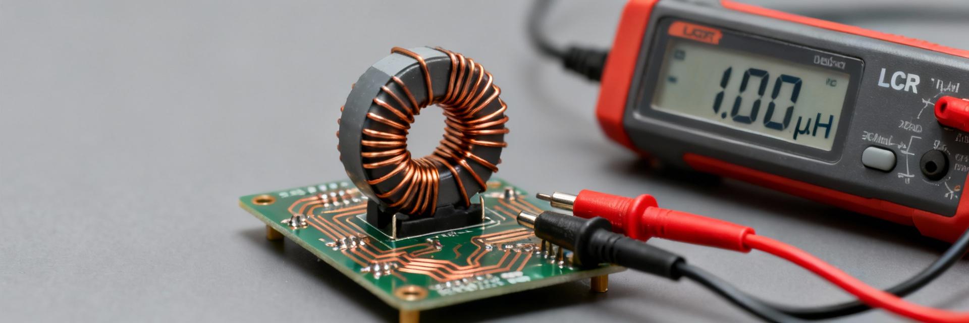
Most SMD power inductors for power stages use ferrite, composite, or metal-alloy cores with wound or stacked windings. Ferrite cores offer high permeability and low cost while metal composite cores raise saturation current and reduce losses. Core material sets permeability, saturation knee, and core loss; tighter packages usually require higher-turn copper or thinner cores, raising DCR and reducing Isat.
1.2 — Key electrical roles: energy storage, filtering, and EMI control
A 4.7µH value often suits medium-frequency buck converters and LC EMI filters where energy per cycle and ripple control matter. At switching frequencies in the hundreds of kilohertz, L controls ripple current and transient response while Isat limits peak handling. Inductance determines stored energy and ripple; DCR governs efficiency; SRF and Q affect behavior near switching harmonics.
2 — Spec-by-spec data deep-dive
Understanding the numerical limits of a 4.7µH SMD power inductor ensures reliability across temperature ranges.
| Parameter | Typical Range (4.7µH) | Critical Impact |
|---|---|---|
| DCR (DC Resistance) | 5mΩ - 150mΩ | Determines I²R conduction losses and heat. |
| Isat (Saturation) | 1.5A - 25A | Peak current limit before inductance drops. |
| Irms (Rated) | 1.0A - 18A | Continuous current based on 40°C temp rise. |
| SRF (Resonance) | 15MHz - 60MHz | Limit for high-frequency switching harmonics. |
3 — How to interpret numbers and pick the right device
3.1 — Step-by-step selection checklist
- Saturation Margin: Ensure Isat is 1.2–1.5× your peak inductor current to prevent core saturation during transients.
- Efficiency Target: Set a DCR budget based on your maximum allowable power loss (P = I² × DCR).
- SRF Check: Ensure the Self-Resonant Frequency is at least 10× your switching frequency.
- Thermal Derating: Check the Irms at your maximum ambient operating temperature, not just at 25°C.
4 — Application examples & PCB practices
PCB layout materially affects inductor temperature: minimize the loop area between the inductor and the switching node. Use multiple vias and wide copper pours for heat spreading, and always measure the inductor's case temperature under full load using thermal imaging.
5 — Selection & validation checklist
What key inductor specs should I prioritize when choosing a 4.7µH SMD power inductor?
Prioritize rated inductance and tolerance, Isat with its test condition, Irms and thermal derating, and DCR for loss budgeting. Also confirm SRF relative to switching harmonics and package height for board fit. Capture these fields in the BOM and validate with in-circuit current sweeps.
How do I estimate ripple current for a 4.7µH SMD power inductor in a buck converter?
Use ΔI ≈ (Vin−Vout)/L · (D/fsw) with D=Vout/Vin. Example: Vin=12V, Vout=5V, fsw=500 kHz, L=4.7µH gives ΔI ≈1.24 A. Apply this to size Isat for peak currents and to select output capacitors.
What on-board tests validate inductor specs before production?
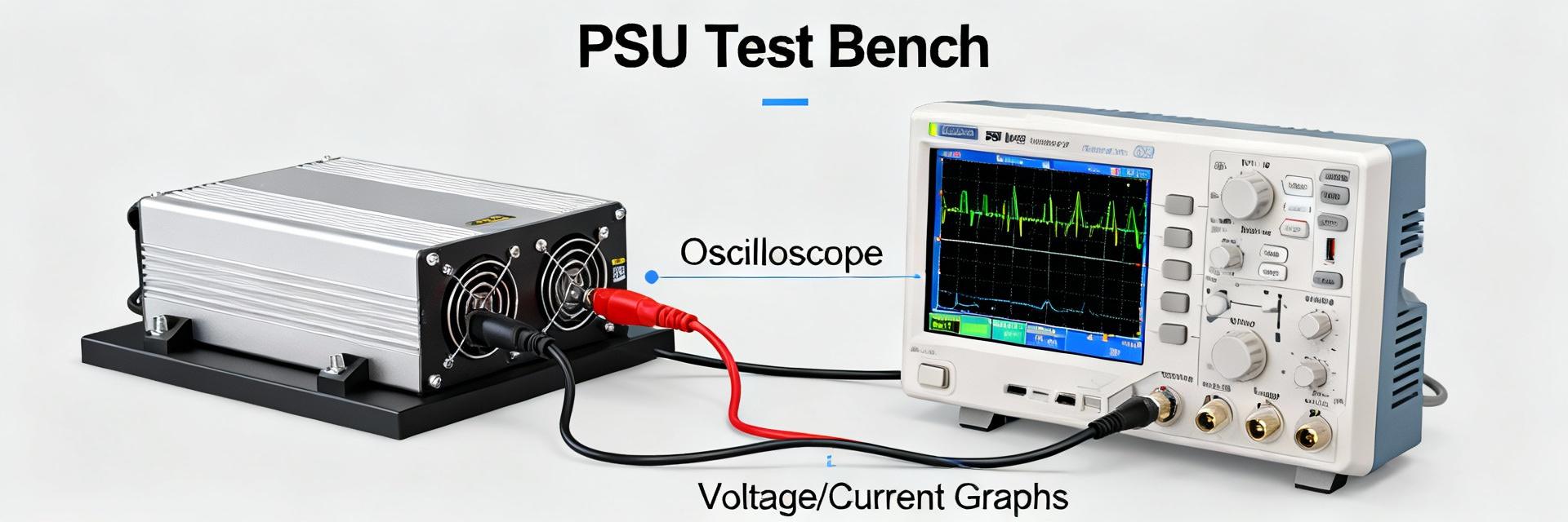
Perform an in-circuit current sweep to detect saturation (look for non-linear current ramps), impedance vs frequency to verify SRF, and thermal-rise testing at rated Irms. Define clear pass/fail criteria tied to inductance change and temperature thresholds.
Why does package size affect the performance of a 4.7µH inductor?
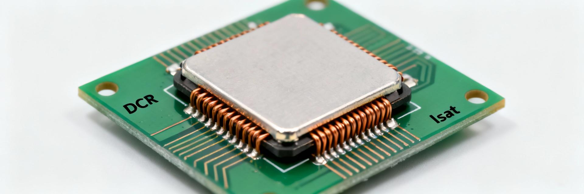
Smaller packages use thinner wire (higher DCR) or smaller cores (lower Isat). When selecting a 4.7µH SMD power inductor, a larger footprint usually provides higher efficiency and better thermal dissipation at the cost of PCB real estate.
Summary: For a 4.7µH SMD power inductor, prioritize Isat for safety and DCR for efficiency. Validate early with thermal imaging and document all test conditions in your BOM.