
Executive Summary: The 7847709010 power inductor is engineered for high-current DC‑DC applications. Key specifications include a 1.0 µH nominal inductance, low RDC (10–15 mΩ), and a robust Irms of 9–10 A, supporting reliable operation up to +125°C.
Product Overview & Key Identifiers
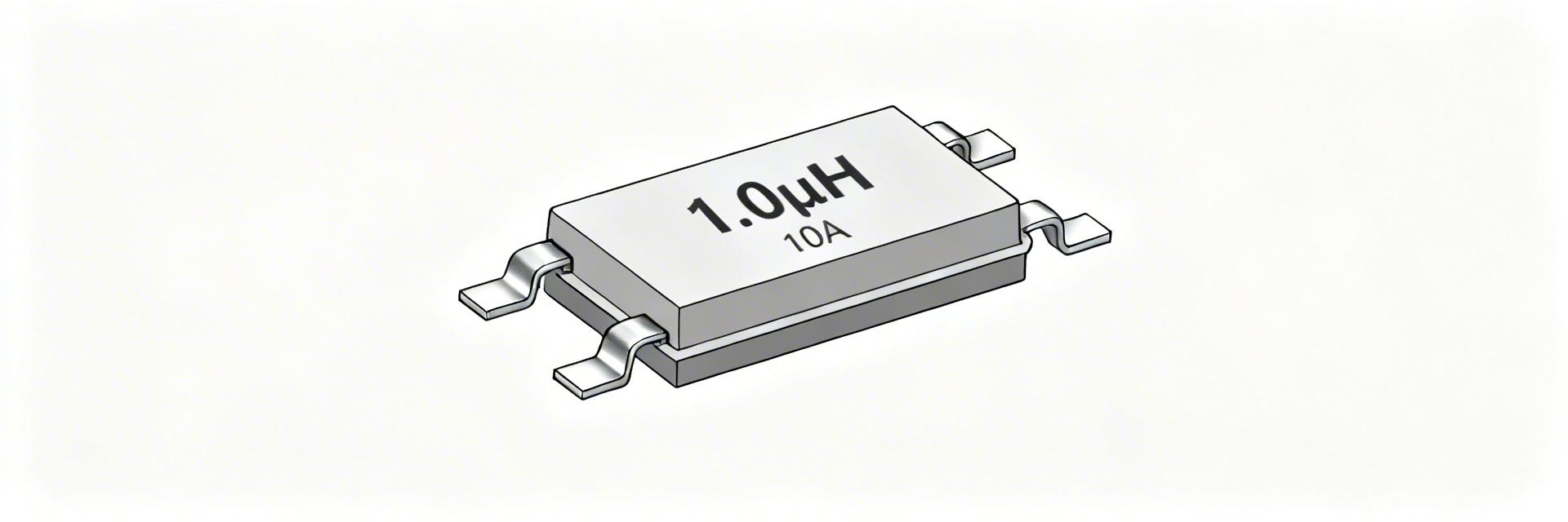
Datasheet At-a-Glance
- Nominal Inductance: 1.0 µH (typical)
- DC Resistance (RDC): ~10–15 mΩ
- Rated Current (Irms): ~9–10 A
- Max Temperature: +125°C
Electrical Characteristics Deep-Dive
Performance Visualization
Comparison of key current ratings and loss factors:
Inductance & Frequency
Nominal L is a low‑frequency reference; real behavior shifts with frequency and DC bias. For high-accuracy SPICE simulations, model the component as a series L + RDC with parallel parasitic capacitance to account for Self-Resonant Frequency (SRF) effects.
Power Loss Calculation
Formula: P_loss ≈ I² × RDC
Ensure Isat ≥ 1.5× expected peak current to maintain linear operation and avoid magnetic saturation during transient loads.
Reliability & Mechanical Limits
Selection & Implementation Guide
1. Sizing Workflow
Define load ripple → Compute ΔI ≈ Vin/(L·fsw)·(1-D) → Verify Isat/Irms against ripple peaks.
2. PCB Layout Dos
Minimize switching loop area; place inductor near MOSFET switching node; use solid ground planes.
3. Bench Testing
Perform thermal imaging at max load; verify inductance stability under full DC bias.
Technical Troubleshooting & FAQ
▶ How do I verify the part fit for a Buck Converter?
Example: For Vin=12V, Vout=3.3V, Iout=8A, fsw=500kHz.
Target ripple ΔI (20-30% of Iout) ≈ 2A.
Check: Is Isat > Peak (8A + 1A = 9A)? If yes, and thermal derating allows 8A Irms, the 7847709010 is a suitable match.
▶ Datasheet QA Checklist & Validation
- Compare measured RDC at room temperature; high values suggest plating issues.
- Test inductance under DC bias; if drops are excessive, upgrade to a higher Isat variant.
- Verify solder fillets and stencil apertures match the recommended land pattern.
▶ EMI Mitigation Tips
Utilize the 7847709010’s shielded construction. Keep the inductor as close as possible to the switching node to minimize radiated noise. Avoid crossing sensitive signal traces beneath the inductor area.


