
Technical Specifications Dashboard
Product Overview & Intended Applications
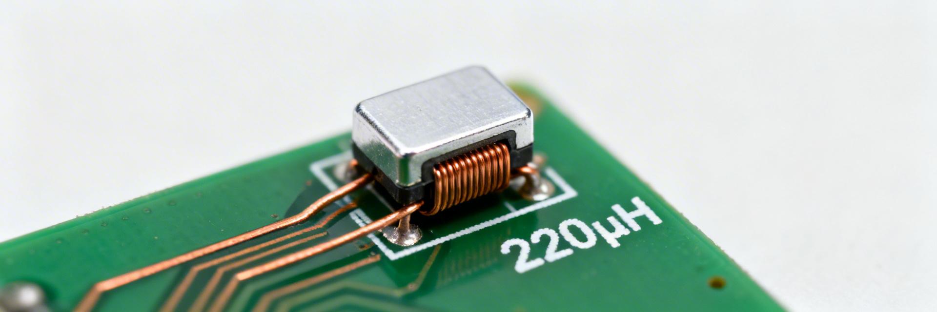
The 784778221 is a shielded SMD power inductor engineered for low-power DC-DC regulation and high-efficiency input/output filtering.
Note: Its compact shielded package makes it ideal for space-constrained rail applications and EMI-sensitive designs by reducing stray coupling on dense boards.
Detailed Electrical Specifications
| Parameter | Datasheet Value | In-Circuit Implication |
|---|---|---|
| Nominal Inductance | 220 µH | Determines ripple current magnitude and control loop stability. |
| Test Frequency | Standard L-measurement | Inductance may shift at actual switching frequencies (e.g., >100 kHz). |
| DCR Max | ≈1.62 Ω | Directly impacts I²R conduction losses and heat dissipation. |
| Rated Current | Low 100s of mA | Defines safe continuous operating current without overheating. |
| Saturation Current | Peak Threshold | Critical for handling startup transients and peak ripple. |
Mechanical & Layout Considerations
Mechanical specs—package dimensions, pad layout, and mounting type—affect reliability. Correct pad sizing and adequate copper area control solder fillet quality and thermal spread. Overlooked clearance can force mechanical rework or degrade performance under load.
- Use thermal vias beneath pads for optimized heat sinking.
- Maximize local copper pour to stabilize winding temperature.
- Avoid placing inductors immediately adjacent to hot power ICs.
Thermal & Reliability Limits
Designers must apply derating—reducing allowable continuous current at elevated ambient temperatures. Ignoring derating risks accelerated magnetic and polymer insulation degradation over the product lifetime.
Test Procedures & Data Interpretation
Reproducing L vs Frequency
Use an LCR meter with suitable test frequencies (100 Hz to 10 MHz). A four-wire Kelvin setup for DCR is mandatory to remove fixture resistance and match datasheet conditions accurately.
Interpreting Impedance Curves
Identify the Self-Resonant Frequency (SRF) to avoid capacitive behavior regions. Read loss charts to estimate core and copper losses at your specific ripple frequencies.
Real-World Validation & Failure Modes
During prototyping, run focused validation tests to catch failure drivers like DCR-driven heating or transient saturation. Diagnose issues by measuring winding temperature and inspecting solder fillets visually.
Common Failure Modes
- Overheating due to excessive I²R losses.
- Solder joint cracks from thermal cycling stress.
- Abrupt inductance collapse during startup transients.
Selection Checklist
- Verify ΔL at peak ripple currents.
- Confirm footprint compatibility and height.
- Review DCR against efficiency budgets.
Summary
- Verify inductance at operating frequency: Confirm L vs frequency to avoid loop surprises and ensure the inductance suits switching frequency requirements.
- Confirm rated and saturation currents: Compare steady-state and transient currents to avoid performance degradation under startup or fault conditions.
- Calculate DCR-driven losses: Estimate I²R losses, design board copper for heat spreading, and apply thermal derating per datasheet guidance.


