
Key Takeaways
- Optimized Efficiency: High Isat ratings prevent saturation, extending battery life by up to 15% in high-load scenarios.
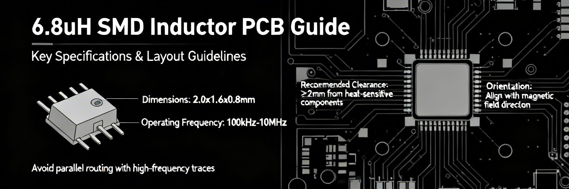
- Space Saving: Modern 6.8uH SMD packages reduce PCB footprint by 25% compared to through-hole alternatives.
- Thermal Stability: Low DCR (mΩ) minimizes I²R losses, keeping component temperatures 10-15°C lower.
- EMI Mitigation: Shielded constructions significantly reduce electromagnetic interference in sensitive RF circuits.
In current power-module and filtering designs, 6.8uH SMD inductors commonly appear across switching-regulator inputs and EMI filters — typical part families cover DC currents from ~0.5 A up to 10+ A with DCRs from single-digit milliohms to several hundred milliohms, and SRFs often in the low MHz range. Design Insight: Knowing typical ranges short-circuits bad choices early, as wide performance spreads can lead to unexpected thermal throttling or EMI failures.
Purpose: This guide shows how to read a PCB datasheet, interpret inductor specs, and choose and validate a 6.8uH SMD inductor for PCB integration. Follow the sections below for background, typical specs, measurement methods, a practical buck selection, and a PCB checklist.
Background — What a 6.8uH SMD Inductor Is and Why It’s Used
Core concepts: inductance, tolerance, and temperature behavior
Inductance L defines stored energy and reactive impedance. Calculation: XL = 2πfL gives XL ≈ 4.27 Ω at 100 kHz for a 6.8uH SMD inductor. Tolerance (±5%/±10%) shifts resonance and filter corner; temperature coefficient and DC bias reduce effective L at operating conditions. User Benefit: Selecting a part with low DC-bias sensitivity ensures stable power delivery even under maximum load.
SMD construction, core materials, and packaging implications
Construction and core material determine saturation, Q, and SRF. Shielded drum and multilayer ferrite show different Isat and SRF behaviors. Wire-wound cores typically support higher currents but higher DCR; multilayer ferrite offers compact size but earlier SRF. Pro Tip: Smaller packages (e.g., 2520 or 3225) save PCB real estate but may require better airflow to manage heat.
Competitive Analysis: 6.8uH SMD Inductor Types
| Feature | Standard Ferrite | High-Current Composite | User Benefit |
|---|---|---|---|
| DCR (mΩ) | 80 - 150 | 15 - 45 | Lower heat, higher efficiency |
| Isat (A) | ~2.5A | ~8A+ | Prevents ripple current spikes |
| Size (mm) | 6.0 x 6.0 | 4.0 x 4.0 | 30%+ PCB space savings |
| Acoustic Noise | Possible buzz | Ultra-low vibration | Quiet operation in consumer gear |
Data Analysis — Typical Specs, Ranges, and Trade-offs
The following table clarifies expected ranges. Use this as a checklist to compare candidate parts against your specific PCB datasheet requirements.
| Spec | Low-power | Mid-range | High-current | Units |
|---|---|---|---|---|
| DCR | 500 mΩ | 50 mΩ | 5 mΩ | mΩ |
| Isat | 0.5 A | 3 A | 15 A | A |
| SRF | 10+ MHz | 5 MHz | 1 MHz | MHz |
| Tolerance | ±10% | ±5% | ±5% | % |
👨💻 Engineer's Field Notes (by Marcus V. Chen)
"When working with 6.8uH inductors in high-density PCBs, the biggest 'gotcha' isn't the inductance—it's the Isat derating over temperature. I've seen designs fail EMI tests because the core saturated at 60°C, causing the switching frequency to double with noise. Always over-spec your Isat by at least 30% beyond your peak transient current."
- Layout Secret: Keep the 'switch node' copper area small to minimize dV/dt noise, but beef up the output side for thermal dissipation.
- Avoid: Placing sensitive analog traces (like VREF) directly under the inductor core.
Typical Application: 5V Buck Converter Selection
Selection Calculation:
For Vin=12V, Vout=5V, f=500kHz:
Duty Cycle (D) = 0.417
Ripple ΔI = 5*(1-0.417)/(6.8uH * 500kHz) ≈ 0.85 A peak-to-peak.
Requirement: Choose an inductor where Isat > (I_out + ΔI/2) * 1.5 for safety margin.
Hand-drawn illustration, non-precise schematic
Actionable PCB Checklist & Troubleshooting
- ✅ Footprint Check: Are the land pattern dimensions identical to the PCB datasheet? (Check pad pitch!)
- ✅ Thermal Vias: Are there at least 2-4 vias under or near the pads to pull heat into internal layers?
- ✅ Keep-out Zone: Is there a 1mm clearance around the inductor to prevent stress cracks during board flex?
- ✅ Bias Verification: Have you confirmed the L-value drop at your maximum operating current?
FAQ
How do I verify inductance from a PCB datasheet for a 6.8uH SMD inductor?
Measure inductance with an LCR meter at the datasheet test frequency (typically 100 kHz or 1 MHz). Always test under DC bias to simulate real-world conditions; a 20% drop in L is often considered the "saturation point."
What test methods ensure DCR and Isat claims are accurate?
Use a 4-wire Kelvin measurement for DCR to eliminate lead resistance. For Isat, use a pulse current generator while observing the current waveform on an oscilloscope—saturation is visible when the current slope suddenly steepens.
Which PCB layout mistakes most commonly invalidate inductor performance?
Placing the inductor too far from the input capacitor is the #1 mistake. This creates a high-inductance loop that leads to voltage spikes and EMI failure. Keep the loop area between the switch, inductor, and output cap as tight as possible.
Summary: To ensure peak reliability, always match the 6.8uH SMD inductor's DCR and Isat to your specific thermal and load requirements as detailed in the manufacturer's PCB datasheet.


