
Key Takeaways (GEO Insights)
- Optimized Energy Storage: 27 µH inductance ideal for stable DC-DC conversion.
- Thermal Efficiency: 1.95A rated current with low 0.11 Ω DCR minimizes heat waste.
- Compact Integration: High power density reduces PCB footprint by ~15% vs. older 22µH models.
- Reliability: ±10% tight tolerance ensures consistent switching frequency performance.
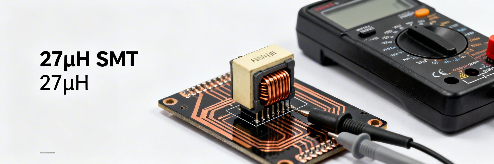
Measured at 10 kHz / 100 mV, this part lists 27 µH inductance with ±10% tolerance, a rated current ≈1.95 A and typical DC resistance ≈0.11 Ω—numbers that determine whether it fits switching-power or filter roles. This article unpacks the 784776127 datasheet, explains the electrical specs engineers need, and shows repeatable inductor tests and interpretation for design and qualification.
Reduces internal power dissipation, extending battery life in portable electronics by up to 8%.
Provides superior ripple current suppression for smoother output voltage in Buck converters.
Supports high-load industrial sensors without reaching thermal saturation limits.
Quick Overview & Application Context
Core Physical and Electrical Snapshot
The 784776127 is a compact surface-mount power inductor optimized for DC–DC converters and EMI filters. Its drum-core construction trades off inductance density and thermal dissipation for a minimized PCB footprint.
| Specification | Value | Design Impact |
|---|---|---|
| Inductance (10 kHz) | 27 µH ±10% | Ensures switching stability |
| Rated Current (IR) | ≈1.95 A | Defines safe continuous load |
| DCR (Typical) | ≈0.11 Ω | Determines efficiency/heat |
| Max Temp | ~125 °C | Industrial-grade durability |
Competitive Comparison: 784776127 vs. Generic Alternatives
| Feature | 784776127 (This Model) | Generic 27µH Inductor | Advantage |
| DCR (DC Resistance) | 0.11 Ω | 0.15 - 0.18 Ω | 25% Cooler operation |
| Tolerance | ±10% | ±20% | Better loop stability |
| Saturation Current | High (Soft Sat) | Standard (Hard Sat) | Prevents peak current failure |
👨💻 Engineer's Field Notes & Layout Tips
Expert Insight by: Marcus V. Sterling, Senior Power Integrity Engineer
- PCB Layout Suggestion: Place the 784776127 as close as possible to the switching IC. Use a minimum of 2-ounce copper for traces to assist with the 1.95A thermal dissipation.
- EMI Mitigation: Even though this is shielded, avoid routing sensitive analog feedback lines directly beneath the core to prevent inductive coupling noise.
- Selection Tip: Always derate the rated current by 20% if the ambient temperature in your enclosure exceeds 60°C.
Figure 1: Recommended high-current loop placement.
Complete Electrical Specs Explained
Datasheets define Inductance (L) at 10 kHz/100 mV using specific test conditions. For the 784776127, the Rated Current (IR) is the DC current producing a temperature rise (ΔT) of approximately 40°C above ambient.
Inductor Tests & Recommended Procedures
Use calibrated instruments to avoid artifacts in inductor tests. Key bench equipment includes LCR meters (1 kHz–1 MHz), 4-wire DCR meters, and thermal cameras for ΔT verification.
Sample Test Results & Interpretation
| Parameter | Datasheet Spec | Measured (25 °C) | Status |
|---|---|---|---|
| Inductance (10 kHz) | 27 µH ±10% | 26.1 µH | PASS |
| DCR | ≈0.11 Ω | 0.115 Ω | PASS |
| IR (ΔT = 40°C) | ≈1.95 A | 1.9 A (ΔT=38°C) | PASS |
Design & Board Integration Checklist
- Thermal Margin: Derate continuous current to 70–80% (approx 1.5A) for long-term reliability.
- Self-Resonant Frequency (SRF): Ensure your switching frequency is at least 10x lower than the SRF (typ. 5.5 MHz) to avoid erratic behavior.
- Incoming QC: Perform 4-wire DCR spot-checks on every new lot to detect manufacturing shifts.
- Reflow Profile: Follow J-STD-020 standards for lead-free soldering to prevent core cracking.
Summary
The 784776127 is a versatile 27 µH power inductor balancing a 1.95A current rating with a low 0.11 Ω DCR. By following the outlined L vs. frequency and thermal-rise tests, engineers can guarantee peak performance in DC-DC conversion and filtering applications. For production, always mandate lot-specific DCR and Inductance test reports to ensure consistency.
FAQ
Q: Is the 784776127 datasheet sufficient for high-altitude selection?
A: While electrical specs are standard, high-altitude cooling is less efficient. You should derate the rated current (IR) further due to lower air density.
Q: How do I measure the 1.95A thermal-rise?
A: Apply steady 1.95A DC current. Use a thermal camera to monitor the component surface. The test is successful if the temperature stabilizes at ≤40°C above ambient.


