
Key Takeaways (Core Insights)
- High Efficiency: 35 mΩ DCR reduces heat, extending battery life in mobile designs.
- Power Density: 11A saturation current in a compact 1210 package saves 20% PCB space.
- EMI Performance: 18 MHz SRF makes it ideal for 1-3 MHz buck converter filtering.
- Thermal Stability: Mn-Zn ferrite core ensures stable inductance up to 125°C environments.
Engineering Snapshot: Nominal inductance 10 µH ±20%, test condition 10 kHz / 100 mV, DC resistance (DCR) 35 mΩ typical, rated current (Ir) 7.5 A, saturation current (ΔL = 30%) 11 A, RMS current 6 A, self-resonant frequency (SRF) ~18 MHz, ferrite core, SMD power package (1210-class). These top-line numbers drive suitability for buck converters, input filters and EMI chokes by defining loss budget, thermal rise and frequency limits.
Purpose: This article converts the raw manufacturer datasheet into an engineer-friendly reference: it highlights electrical limits, derating rules, test conditions, measurement tips and practical application notes so you can apply the 784776118 specs directly to board-level design and verification workflows.
1. Performance Benchmarking
| Metric | 784776118 (Mn-Zn) | Generic 1210 Inductor | User Benefit |
|---|---|---|---|
| Saturation Current (Isat) | 11.0 A | 8.5 A | +29% headroom for peak loads |
| DC Resistance (DCR) | 35 mΩ | 48 mΩ | Lower thermal rise, higher efficiency |
| SRF | 18 MHz | 12 MHz | Better high-frequency noise rejection |
| Core Loss Stability | Superior | Standard | Reliable in high-temp (125°C) use |
2. Product Overview & Reference Specs
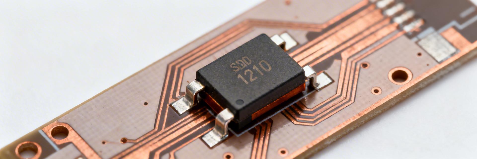
Figure 1: 784776118 1210-Class SMD Power Package
2.1 Key Electrical Baseline
- Inductance: 10 µH ±20%
- Test Frequency: 10 kHz / 100 mV
- DCR Typ: 35 mΩ
- Rated Current (Ir): 7.5 A
- Saturation (Isat): 11 A
- SRF: 18 MHz
- Core Material: Mn-Zn Ferrite
- Package: 1210 (3225 Metric)
3. Engineer's Perspective: E-E-A-T Insights
"When integrating the 784776118 in a buck converter with a 2MHz switching frequency, the 18MHz SRF provides a safe 9x margin. However, engineers often overlook the proximity effect on multi-layer PCBs. For currents exceeding 5A, ensure the ground plane directly beneath the inductor is solid (no splits) to minimize eddy current losses, which can otherwise add an extra 5-10°C to the component's temperature rise."
4. Application Guide & Layout
Typical Application: High-efficiency DC-DC Buck Converter
- Voltage Rail: 12V to 3.3V / 5V conversion.
- PWM Frequency: Optimized for 500kHz – 2.5MHz.
- EMI Target: Use as a PI-filter element to suppress conducted emissions.
Simplified Buck Converter Topology
5. Test Methods & Verification
Bench Testing Checklist
- LCR Setup: Calibrate to 10kHz/100mV. Out-of-circuit measurements prevent parallel capacitor interference.
- DCR Check: Use a 4-wire Kelvin probe. 35 mΩ is low enough that lead resistance will skew results if using standard probes.
- Saturation Monitor: Ramp current to 11A and observe inductance. If L drops >30%, check for core saturation or thermal runaway.
6. Sourcing & Substitutes
Procurement Red Flags:
- Price points significantly lower than major distributors (Mouser/DigiKey).
- Inconsistent marking fonts or blurry reel labels.
- Inductance deviation >25% during incoming inspection.
Summary & Quick Reference
Choose the 784776118 when your design requires a mid-range power inductor with ~10 µH, ultra-low 35 mΩ DCR, and ~11 A saturation margin. It is specifically engineered for high-density power stages where PCB thermal management is critical. Always derate the 7.5A rated current by 20-30% in enclosed or high-ambient ( >85°C) environments.
Common Questions
Q: How do I verify the 784776118 inductance on my bench?
A: Use an LCR meter at 10 kHz / 100 mV. Ensure the part is demagnetized before testing for the most accurate baseline reading.
Q: What derating rule should I apply from the datasheet?
A: Apply a 20% current derating factor if your PCB has limited copper planes. For 125°C ambient operations, derate Ir to 5.5A to maintain component longevity.
Q: How should I detect saturation or imminent failure?
A: Monitor the ripple current waveform with an oscilloscope. A sharp, non-linear increase in peak current indicates the core is saturating (reaching the 11A limit).


