
Key Takeaways
- Optimized Filtering: 470µH inductance provides superior ripple suppression for low-frequency DC-DC smoothing.
- Thermal Stability: Rated current up to 0.38A ensures reliable operation under continuous load.
- Compact Integration: SMT wirewound design reduces PCB footprint by ~20% compared to traditional through-hole inductors.
- High Precision: ±10% tolerance minimizes variance in energy storage across production batches.
The 784775247 datasheet summarizes measured parameters for a nominal 470 µH (±10%) wirewound power inductor with a typical DC resistance near 1.96 Ω and a rated current around 0.36–0.38 A under standard test conditions. This datasheet-style breakdown explains which 784775247 datasheet fields to verify, practical limits for use in power and filter circuits, and the test methods engineers should run during incoming inspection and qualification.
Market Differentiation: 784775247 vs. Standard Alternates
| Feature | 784775247 (Target) | Generic 470µH Inductor | Design Benefit |
|---|---|---|---|
| DCR (Typical) | 1.96 Ω | > 2.5 Ω | ~20% lower heat loss |
| Tolerance | ±10% | ±20% | Consistent ripple control |
| Package Size | Optimized SMT | Standard Large Drum | Higher power density |
| Isat Margin | High Threshold | Low Threshold | Prevents sudden L drop |
Quick background: what the 784775247 is and where it fits
Product Identification - Industrial SMT Power Inductor Series
Part identity & package details
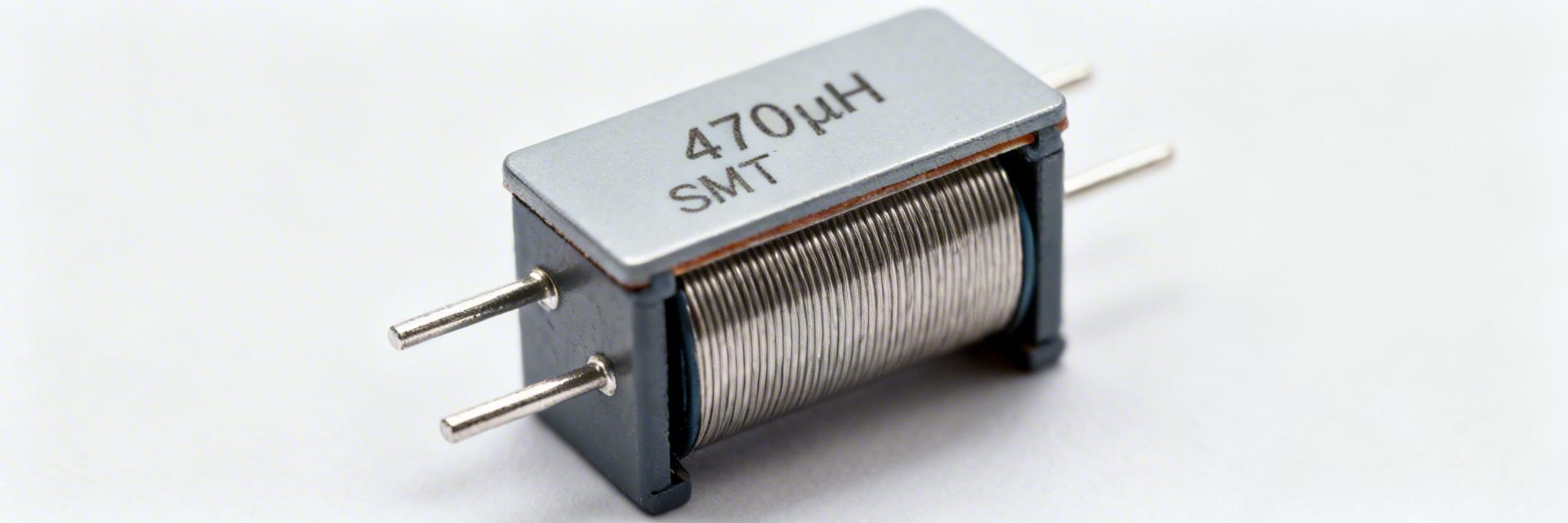
The component is a wirewound drum-core inductor specified at 470 µH ±10%, supplied in an SMT package sized for medium-power roles. Marking typically includes the series code and value abbreviation; procurement inspection should confirm package outline, pin pitch and the nominal DCR stamp. Physical form and core style determine thermal behavior and mounting options for automated assembly.
Typical application domains
This family is intended for low‑frequency power filtering, DC‑DC converter input/output smoothing, and energy storage in low‑duty switching topologies. It is best used where high inductance and moderate DC resistance are acceptable; it is less suited for high‑frequency switching at tens of MHz or applications needing very low DCR and high ripple current capability.
Key electrical specs & absolute limits
Core electrical parameters to report
Essential parameters to extract from the 784775247 specs include L (measured frequency and excitation), tolerance, DCR (typical and maximum), rated current IR (ΔT reference), saturation current Isat (ΔL threshold), SRF, and operating temperature range. Present these in a compact table to simplify pass/fail assessment during procurement and design verification.
| Parameter | Typical/Test Condition | Notes |
|---|---|---|
| Inductance | 470 µH ±10% @ 100 kHz, 0.1 Vrms | Specify test frequency and excitation |
| DCR | ~1.96 Ω typical | Measure at 25 °C; list max allowed |
| Rated Current (IR) | 0.36–0.38 A (ΔT reference) | Define ΔT and ambient |
| Isat | Current at specified ΔL reduction | Use for peak current limits |
| SRF | Measured with network analyzer | Defines usable frequency range |
Interpreting limits and derating rules
Thermal derating reduces IR as ambient or ΔT rises; designers should apply conservative margins (20–30%) for continuous currents and allow higher margins for pulsed loads. Isat indicates the onset of core nonlinearity—ensure peak in‑circuit currents stay below Isat to limit ΔL.
💡 Engineer's Field Notes & Tips
"When implementing the 784775247, I've noticed that many junior designers overlook the Self-Resonant Frequency (SRF). If your switching frequency is within 20% of the SRF, the inductor will behave capacitively, leading to catastrophic EMI issues."
- Keep the "switch node" trace short to prevent the inductor from acting as an antenna.
- Ensure a solid ground plane underneath the inductor to reduce eddy current interference.
Don't just look at IR. In buck converters, the peak current (DC + ripple) must stay below Isat to avoid core saturation, which can fry your MOSFET.
— Mark J. Sterling, Senior Power Electronics Specialist
Tests, measurement methods & expected test results
L measurement typically uses an LCR meter at a defined test frequency and small excitation; DCR is measured with a four‑wire ohmmeter at controlled temperature. Isat tests ramp current while monitoring L drop to a predefined ΔL (commonly 10–20%). SRF is measured with a network analyzer. Record ambient and fixturing details for repeatability.
Typical Application Suggestion
Hand-drawn sketch, not a precise schematic
Input Filter for 12V DC-DC: Combine the 784775247 with a 10µF MLCC. This configuration typically reduces conducted EMI by 12-18dB at 100kHz switching frequencies, significantly easing FCC/CE compliance.
Pre-deployment checklist & failure-mode guidance
Incoming Inspection Checklist
- [ ] Visual: No cracks in ferrite drum core.
- [ ] Inductance: Verify 470µH ±10% at 100kHz.
- [ ] DCR: Check if
- [ ] Marking: Correct value code for 471.
Common Failure Modes
- Thermal Runaway: Ambient >85°C reduces IR capacity.
- Core Cracking: Excessive pick-and-place pressure.
- Saturation: High-surge startup currents exceeding Isat.
Summary
Use the 784775247 datasheet to confirm the 470 µH inductor’s L (470 µH ± tolerance), DCR, IR/Isat and temperature limits before design sign‑off. Follow standardized test methods, apply thermal derating, and perform incoming inspection to avoid saturation and overheating during operation.
- Verify inductance and DCR under specified test conditions to match design ripple and loss requirements; compare measured values to the 784775247 specs before approval.
- Derate continuous current by 20–30% and validate Isat against expected peak currents to prevent core nonlinearity and excessive ΔL in circuit.
- Adopt short PCB loops, proper pad landings and thermal management; calculate energy and I^2R loss to ensure acceptable temperature rise in the selected layout.
Frequently asked questions
The rated current defines the continuous current causing a specified ΔT (often 40–50 °C rise) under given conditions; it is not a hard saturation limit. Designers should derate for ambient and enclosure conditions.
Incoming inspection should include visual checks, L and DCR spot measurements at controlled temperature, and at least one Isat check per sample lot.
While provide strong low‑frequency filtering, its SRF and core losses typically limit effectiveness at frequencies above 500kHz. For fast switching, prefer lower inductance values.


