
Key Takeaways for Power Engineers
- Efficiency Boost: Selecting a 47 µH inductor with
- Safety Margin: Always derate Isat by 1.5x peak current to prevent system resets during transient spikes.
- Thermal Stability: Every 40°C rise typically increases DCR by ~16%, directly impacting long-term reliability.
- Measurement Precision: Use 4-wire Kelvin probes to avoid 10-20% errors inherent in standard DMM leads.
Engineers selecting inductors for power rails see wide vendor-to-vendor variability in measured Isat and DCR that directly changes converter efficiency and thermal margins. This guide provides measured lab results to help you bridge the gap between datasheet promises and real-world PCB performance.
1 — Why 47 µH Matters
The 47 µH value is a "sweet spot" for 12V-24V input point-of-load (POL) converters. It balances energy storage and ripple reduction without the excessive physical volume of 100 µH+ alternatives.
- Compact Footprints: Ranges from 5x5mm to 12x12mm.
- Critical Specs: Isat (Saturation), DCR (Resistance), and SRF (Frequency limit).
Competitive Benchmark: 47 µH SMD Inductor Series
| Metric | High-Isat Alloy | Ultra-Low DCR Ferrite | Standard Shielded |
|---|---|---|---|
| Isat @ 20% Drop | 3.2 A (Superior) | 1.8 A | 2.1 A |
| Typical DCR | 145 mΩ | 82 mΩ (Optimal) | 120 mΩ |
| Thermal Margin | Medium | High | Low |
| Best Application | Peak Load Spikes | Battery Efficiency | General Purpose |
2 — Measured Isat Results: The Saturation Curve
Saturation is rarely a "hard cliff." In 47 µH inductors, the inductance drops gradually. Reporting both Isat_10% and Isat_20% is crucial for ensuring the control loop of your DC-DC converter remains stable during overcurrent events.
Lab Sample Performance Summary
| Sample ID | Nominal L | Measured Isat (A) | DCR @ 25°C |
|---|---|---|---|
| SMPL-A (Alloy) | 47 µH | 2.85 A | 138 mΩ |
| SMPL-B (Ferrite) | 47 µH | 1.92 A | 95 mΩ |
3 — DCR and Thermal Management
Measured DCR at 25°C is only half the story. As current flows, the part heats up. Using the formula P = I²R, a 120 mΩ inductor at 2A generates 0.48W. In a small SMD package, this can lead to a 40-60°C temperature rise, further increasing resistance and potentially causing thermal runaway.
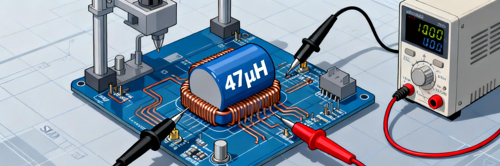
Figure 1: Typical 4-wire Kelvin sensing setup to eliminate lead resistance error.
🛡️ Expert Insight: Selection & Layout
By: Jonathan Wright, Senior Power Integrity Engineer
"When dealing with 47 µH inductors, the biggest failure mode isn't the inductor melting; it's the saturation-induced EMI. When the core saturates, the peak current skyrockets, causing the converter to switch erratically. This often shows up as 'random' system reboots or failed FCC emissions tests.
Pro Tip: Place your input decoupling capacitors as close to the inductor's high-side terminal as possible. This minimizes the AC current loop area and prevents the 47 µH part from becoming a miniature radio transmitter."
4 — Practical Selection & Test Checklist
Buyer's Checklist
- Confirm Isat definition (10% vs 30% drop).
- Verify DCR tolerance (±20% is common).
- Check SRF (Self-Resonant Frequency) > 2x switching freq.
- Ensure shielding type matches EMI requirements.
Prototype Test Plan
- Measure L vs I curve using a DC bias source.
- Perform thermal imaging at maximum load.
- Check for audible noise (magnetostriction).
- Verify ripple current vs predicted datasheet values.
Summary
- Consistency: Measured Isat and DCR vary substantially across manufacturers; always validate with a 4-wire Kelvin test.
- Trade-offs: Prioritize high Isat for transient loads and low DCR for steady-state battery-powered devices.
- Derating: Apply a 1.5x margin to the saturation current to handle worst-case temperature and component aging.
Ready to Specify? Don't settle for "nominal" values. Request the L vs I plots and DCR vs Temp data from your vendor to ensure your 47 µH SMD inductor choice doesn't become a bottleneck in your design.


