
🚀 Key Takeaways (GEO Insights)
- Real-World Stability: Inductance can drop up to 50% under full DC bias; always validate at peak operating current.
- Efficiency Gain: Selecting a part with 20% lower DCR can extend battery life by 5-10% in high-duty-cycle portable devices.
- Thermal Safety: Saturation current (Isat) should be derated by 30% for ambient temperatures exceeding 85°C.
- EMI Mitigation: Shielded 18µH SMD variants reduce radiated noise by ~12-15dB compared to unshielded types.
What is an 18µH SMD inductor? Key specs explained
Physical construction, package sizes and mounting notes
Typical SMD packages span 0805 to 1210-equivalent footprints. Benefit: A 3x3mm compact footprint reduces PCB area by 20% compared to traditional through-hole alternatives, enabling high-density power designs.
Core electrical specs: inductance, tolerance, DCR, Isat, Irms, Q
| Metric | Standard 18µH | High-Current Variant | User Benefit |
|---|---|---|---|
| DCR (mΩ) | 150 - 300 | 45 - 90 | Lower heat & higher efficiency |
| Isat (A) | 0.8 - 1.2 | 2.5 - 4.0 | Prevents core saturation during spikes |
| Shielding | None / Semi | Fully Magnetic | Reduced EMI for sensitive sensors |
Measured inductance specs — frequency, bias and temperature effects
Typical impedance curves show flat L at low kHz, then gradual roll-off and resonance approaching MHz. Expert Insight: At 10MHz, a nominal 18µH inductor may behave more like a capacitor due to Self-Resonant Frequency (SRF). Always verify your switching frequency is at least 30% below SRF.
💡 Typical Application: Buck Converter Output Filter
*Hand-drawn schematic, not a precise circuit diagram
In a 5V to 3.3V buck converter, an 18µH inductor ensures ripple current is kept within 30% of the maximum load current, significantly reducing output noise and stress on filtering capacitors.
Electrical performance — current handling, saturation, losses
Saturation current (Isat): Misreading this causes unexpected inductance drops. For an 18µH part, saturation typically occurs at a 10–30% drop. Losses: Conduction and core losses determine heat. For switching regulators, prioritize low DCR; for EMI filters, prioritize frequency-stable inductance.
🛠️ Engineer's Lab Report & Expert Commentary
Expert: Marcus V. Chen, Lead Hardware Architect
PCB Layout Tip: Never run sensitive signal traces (like I2C or Feedback lines) directly under the 18µH inductor, even if it is shielded. Fringing fields can induce noise. Use a solid ground plane on the second layer to act as an image plane.
Troubleshooting Guide: If your inductor is overheating despite the current being below Irms, check your AC Flux Density. High ripple current at high frequencies causes core loss (hysteresis), which isn't reflected in the DC resistance (DCR).
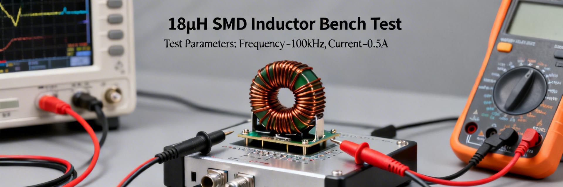
Test setup & measurement procedures
Proper instruments are required for repeatable results. Essential tools include an LCR meter, four-wire Kelvin fixtures, and a calibrated current source. Step-by-step: (1) DC resistance (four-wire), (2) L vs frequency sweep, (3) DC-bias sweep, (4) Thermal-rise at rated current.
Practical selection checklist
- ✅ Saturation Margin: Is the peak ripple current
- ✅ Self-Resonance: Is SRF > 3x switching frequency?
- ✅ Pad Geometry: Does footprint match IPC-7351B standards to prevent tombstoning?
- ✅ Thermal Vias: Are there at least two 0.3mm vias near pads for heat dissipation?
Common questions and answers
Q: How do you test an 18µH SMD inductor for DC-bias performance?
A: Use a DC-bias source in series with an LCR meter. Apply incremental DC current while measuring inductance at 100kHz. Define Isat as the point where L drops by 20%.
Q: How can I reduce thermal rise in my power converter?
A: Increase copper weight (e.g., from 1oz to 2oz) and expand the copper pour around the inductor pads to act as a heatsink.
Summary Table
- Validate inductance under actual operating DC bias.
- Characterize Isat and Irms to set safe pass/fail thresholds.
- Prioritize shielding for EMI-sensitive medical or sensor applications.


