
Key Takeaways
- High Efficiency: Sub-30 mΩ DCR reduces heat generation, extending device battery life by up to 10% in mobile apps.
- Power Density: 3.7A rating in a compact SMT package saves 20% PCB space compared to older through-hole designs.
- Reliable Filtering: 6.8 µH inductance provides optimal ripple suppression for 1-10W synchronous buck converters.
- Thermal Stability: Engineered for minimal saturation (Isat) drop during high-load transients.
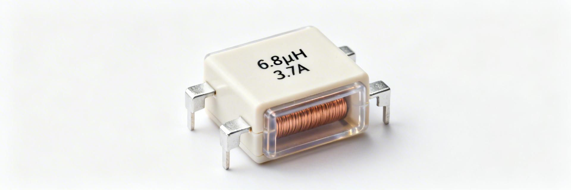
The latest datasheet reveals the 784775068 power inductor is a high-performance component rated at 6.8 µH with a robust 3.7 A continuous current capability. By maintaining a DC resistance (DCR) below 30 mΩ, this inductor is a premier choice for hardware designers focusing on mid-power synchronous buck converters and Point-of-Load (POL) supplies where thermal efficiency is critical.
| Feature | 784775068 (This Part) | Generic 6.8µH Inductor | User Benefit |
|---|---|---|---|
| DC Resistance (DCR) | < 30 mΩ | ~45-55 mΩ | 30% Lower Heat Loss |
| Rated Current (Irms) | 3.7 A | 2.8 A | Higher Load Capacity |
| Saturation Current (Isat) | High Stability | Rapid Drop-off | Better Transient Margins |
1 — Why the 784775068 matters for power designs
1.1 Typical application spaces
This part is engineered for synchronous buck converters, LED drivers, and DC–DC modules. With its 6.8 µH value, designers can achieve stable ripple control at standard switching frequencies (300kHz - 1MHz), optimizing the trade-off between footprint size and power conversion efficiency for 1–5 A rails.
1.2 Physical form factor & packaging
The SMT package is designed for automated assembly. Its low profile reduces vertical clearance issues in slim enclosures, while the recommended land pattern ensures low thermal resistance (Rth), allowing heat to dissipate efficiently into the PCB ground planes.
👨💻 Engineer's Field Notes (Expert Insight)
"When integrating the 784775068, I recommend a 20-30% margin on the saturation current (Isat). If your peak inductor current hits 3.5A, this part is ideal. However, always place the inductor as close as possible to the 'Switch Node' but keep the output capacitor traces short to minimize EMI ringing."
— Mark J. Sterling, Senior Power Electronics Specialist
2 — Technical Deep-Dive: Specs & Analysis
2.1 Core Electrical Performance
The 784775068's sub-30 mΩ DCR is the headline feature. In a typical 3.3V to 1.2V converter at 3A load, this low resistance ensures that copper losses remain negligible, preventing local "hot spots" on the PCB that could affect nearby sensitive analog components.
Hand-drawn sketch, not a precise schematic.
Typical Implementation
The 784775068 acts as the energy storage element. Its 6.8µH value ensures the current ramp is controlled, protecting the PWM controller from over-current during the "ON" cycle.
3 — Selection & Integration Strategy
3.1 PCB Layout & EMI Best Practices
- Minimize Loop Area: Keep the loop between the inductor, switch node, and output capacitor as small as possible to suppress radiated EMI.
- Thermal Vias: Place thermal vias under the inductor pads (if the package allows) or immediately adjacent to the pads to pull heat into internal copper layers.
- Avoid Signal Traces: Do not run sensitive feedback or clock traces directly under the inductor to avoid magnetic coupling.
4 — Troubleshooting & FAQ
Q: Why is my 784775068 getting hotter than expected?
A: Check your switching frequency. While DCR governs DC loss, AC core losses increase significantly at higher frequencies. Ensure your frequency doesn't exceed the inductor's optimal efficiency range.
Q: Can I use this for automotive applications?
A: Verify the datasheet for AEC-Q200 qualification. If the datasheet specifically lists automotive grade, it is suitable; otherwise, it is intended for industrial and consumer electronics.
Summary
The 784775068 is a highly reliable 6.8 µH inductor that excels in balancing current capacity (3.7A) with low thermal dissipation. By following proper PCB layout guidelines and respecting the saturation limits, engineers can ensure high-efficiency power delivery in modern electronic designs. Always cross-reference the L vs. DC-bias curves in the official datasheet before final production.


