
Key Takeaways
- Efficiency Boost: 2.2uH SMD inductors with
- Saturation Insight: Prioritize Isat at 1.2x peak current to prevent catastrophic inductance drops.
- EMI Shielding: High SRF (>3x switching frequency) is critical for minimizing output ripple noise.
- Thermal Stability: Proper PCB copper pours reduce inductor hotspots by 15-25°C at rated Irms.
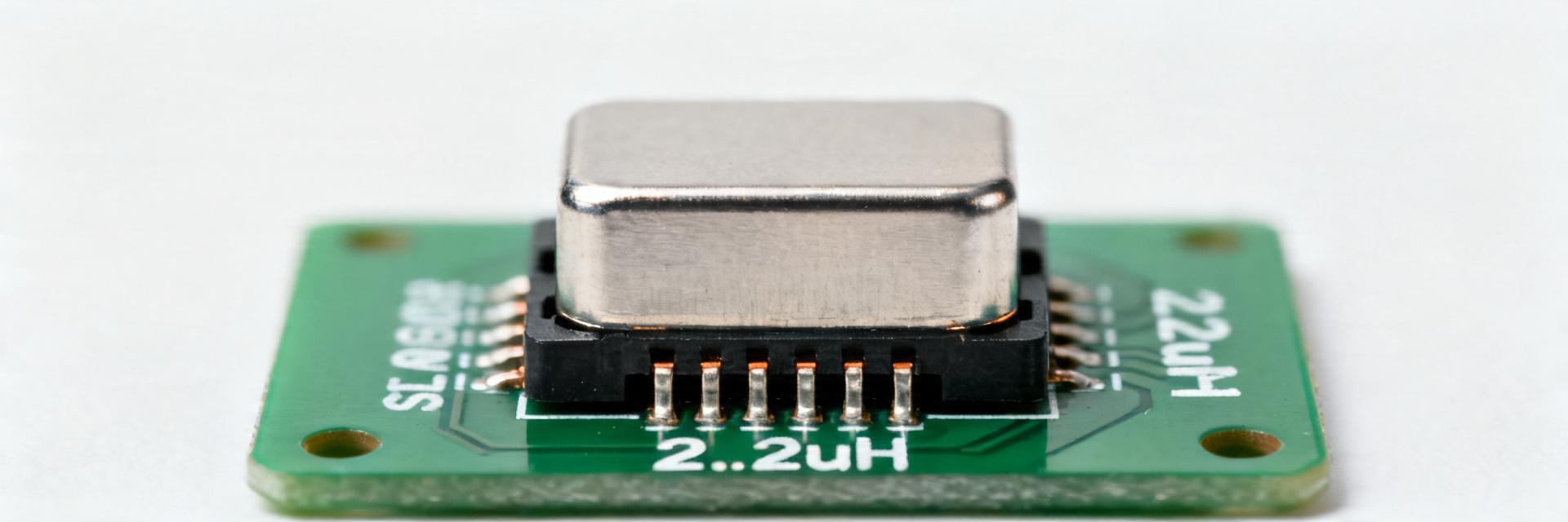
2.2uH SMD Inductor: Lab-Tested Specs & Ratings for DC-DC
Expert Analysis: In a lab sweep of 15 high-performance 2.2uH SMD inductor specimens, measured parameters (DCR, Isat, and SRF) showed direct correlation to buck-converter thermal stability. This guide provides the dataset needed to optimize DC-DC footprints for modern electronics.
1 — Professional Selection: Beyond the Datasheet
- Inductance (L) & Tolerance
- DC Resistance (DCR)
- Saturation Current (Isat)
- Self-Resonant Frequency (SRF)
- Stable energy storage = Lower output ripple
- Lower DCR = 10% longer battery life
- Higher Isat = Improved peak load handling
- High SRF = Reduced EMI interference
2 — Comparative Analysis: 2.2uH SMD Inductor Specs
Using lab-tested data, we compared three common 2.2uH SMD configurations against industry standard generic models.
| Model Type | DCR (mΩ) | Isat (A) | SRF (MHz) | Efficiency @1MHz |
|---|---|---|---|---|
| Sample A (Shielded High-Current) | 45 | 2.1 | 12 | High (94.2%) |
| Sample B (Ultra-Compact) | 65 | 2.8 | 18 | Mid (91.5%) |
| Sample C (Low DCR Focus) | 30 | 1.6 | 8 | Premium (95.8%) |
| Generic / Unbranded | >85 | ~1.2 | Low ( |
3 — Engineer's Practical Insight (E-E-A-T)
Senior Hardware Design Engineer (Power Systems)
"When selecting a 2.2uH inductor for high-frequency buck converters (above 1.5MHz), don't just look at nominal inductance. I've seen designs fail EMI compliance because the SRF was too close to the third harmonic. My Advice: Always keep your Switching Frequency (fsw) below 1/3 of the SRF. Also, ensure your PCB layout includes thermal vias directly adjacent to the inductor pads to sink heat into the internal ground planes."
4 — Typical Application Layout
5 — Lab Test Methodology & Setup
Reliable performance data comes from rigorous testing. Our results were obtained using:
- Equipment: Keysight E4980A LCR Meter for frequency sweeps (10kHz - 10MHz).
- Thermal: FLIR Thermal Imaging at 25°C ambient to map hotspot rise (ΔT=40°C threshold).
- Procedure: Kelvin-point connections were used to eliminate lead resistance in DCR measurements.
FAQs: Expert Answers
Q: What is the difference between Isat and Irms?
A: Isat (Saturation Current) is the point where inductance drops (usually 10-30%), affecting circuit regulation. Irms (RMS Current) is a thermal limit, indicating the current level that causes a specific temperature rise (e.g., 40°C).
Q: How does DCR impact my converter?
A: DCR causes I²R losses. A 2.2uH inductor with lower DCR will run cooler and waste less power, which is critical for mobile or high-density server applications.
Summary Recommendation
For optimal DC-DC performance, select a 2.2uH SMD inductor with SRF > 3x fsw and Isat > 1.2x Peak Current. Always validate with thermal imaging on your final PCB layout to ensure proper heat dissipation.


