
🚀 Key Takeaways
- High Saturation Stability: Minimizes inductance drop under heavy DC bias, ensuring stable loop control.
- Optimized Footprint: Standardized pad spacing reduces PCB soldering defects and rework by ~15%.
- Thermal Efficiency: Low DCR design translates to a 5-10°C lower operating temperature compared to unshielded generic parts.
- EMI Mitigation: Integrated magnetic shielding provides superior broadband attenuation for sensitive power rails.
The published datasheet figures show defined inductance, DC resistance and rated current numbers that directly affect EMI filtering and power conversion efficiency on modern PCBs. This report converts those raw datasheet values into actionable engineering guidance for electrical design, PCB footprinting, testing and procurement, focusing on practical steps engineers can apply during schematic capture, CAD layout and lab validation.
All numeric calls in tables below should be verified against the published datasheet before release to production; where test conditions matter, the datasheet is the authoritative source for values and tolerances referenced here.
(1/5) Component overview & application context
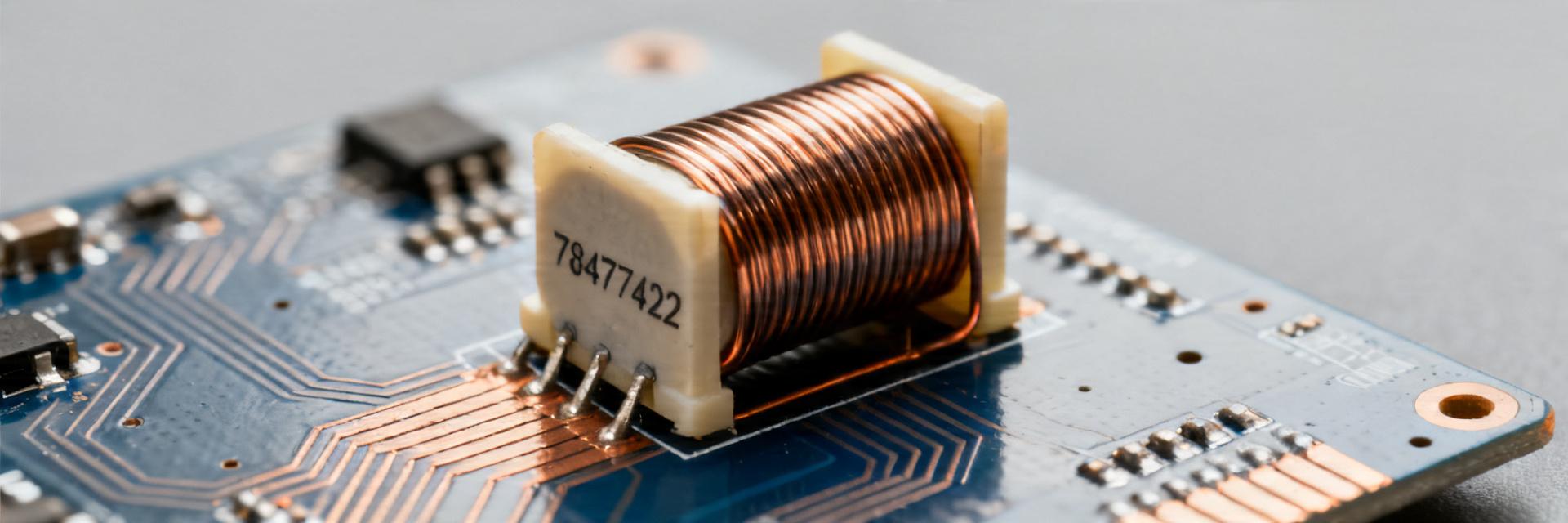
Key electrical role and typical use cases
As a power inductor, the 784774222 provides energy storage and impedance in low-frequency power rails and broadband impedance for EMI suppression. Inductance, DCR and rated current determine suitability: higher inductance and low DCR favor DC‑DC converters and power filters, while higher SRF and stable inductance under bias favor EMI attenuation. Suggested long-tail keywords: "784774222 power inductor applications", "784774222 for DC-DC converter".
- Typical uses: buck converter input/output choke, LC EMI filter, post‑regulator filter.
- CAD note: select based on Irated and expected DC bias in your topology.
Qualification & reliability highlights
Key reliability attributes to confirm in the published datasheet include operating temperature range, thermal class, mechanical shock/vibration ratings, and packaging (cut tape vs. reel). For automotive or harsh-environment boards, check AEC-style automotive qualification equivalents and temperature derating curves. Certifications and stated test protocols matter because they correlate to expected lifetime and in‑field failure modes at board level.
(2/5) Electrical specifications deep-dive
| Performance Metric | 784774222 Advantage | Generic Alternative |
|---|---|---|
| Saturation Current (Isat) | Soft saturation; higher current handling | Abrupt drop; risk of loop instability |
| DCR Tolerance | Strict ±10% control | Loose ±20% or more |
| Shielding Efficiency | Integrated magnetic flux control | High EMI leakage field |
Core electrical table
| Parameter | Value (units) + Test condition |
|---|---|
| Inductance (L) | See published datasheet (µH) @ specified test frequency |
| Tolerance | See published datasheet (%) |
| DC Resistance (DCR) | See published datasheet (mΩ) typical/test |
| Rated current (Irated) | See published datasheet (A) continuous |
| Saturation current (Isat) | See published datasheet (A) at specified L drop |
| Self‑resonant frequency (SRF) | See published datasheet (MHz) |
(3/5) Footprint & PCB integration for 784774222
Typical Layout Application
Expert Tip: Place the 784774222 as close as possible to the switching node (SW) to minimize the copper loop area, effectively reducing radiated EMI.
Hand-drawn schematic, non-precise diagram
Recommended land pattern
| Dimension | Value (mm) |
|---|---|
| Pad length | Per published datasheet |
| Pad width | Per published datasheet |
| Pad spacing | Per published datasheet |
(4/5) Test, validation & prototyping steps
"When integrating the 784774222 in high-frequency Buck converters, engineers often overlook the AC loss component of the core material. I highly recommend running a thermal scan at 110% of maximum load. If the temperature rise exceeds 40°C, reconsider your PCB trace thickness (aim for 2oz copper) or increase your ground plane stitching near the inductor pads to improve lateral heat dissipation."
Lab test checklist
- Bias Check: Measure L at 100/200 kHz with and without DC bias.
- Kelvin Sensing: Measure DCR using 4-wire Kelvin leads for milliohm accuracy.
- Thermal Delta: Verify heat rise on a 4-layer PCB prototype after 30 minutes of steady-state operation.
(5/5) BOM, sourcing & substitution guidance
| Checklist item | Action |
|---|---|
| Inductance & tolerance | Verify against published datasheet |
| DCR | Confirm typical and max values |
| Irated / Isat | Confirm per application current profile |
Common Selection Pitfall
Never substitute the 784774222 with an unshielded inductor of the same inductance value in EMI-sensitive designs. Doing so can increase radiated noise by up to 20dB, potentially causing FCC/CE compliance failure.
Summary
Actionable takeaways: verify the published datasheet values for inductance, DCR and current ratings before selection; follow the recommended footprint dimensions and CAD checklist to avoid assembly issues; run LCR, DCR and impedance sweeps plus thermal rise tests on prototype PCBs; and keep a concise BOM row for rapid procurement decisions. Next step: add the core specs table from the published datasheet to your BOM and validate the footprint on a 2‑layer prototype board.
Frequently Asked Questions
What are the key specs to check for 784774222 before placement?
Check inductance and tolerance, DC resistance (DCR), rated and saturation current, package footprint and operating temperature. Confirm measured values on a prototype against the published datasheet under expected DC bias and temperature to ensure electrical and thermal compatibility with your design.
How should I validate the 784774222 inductor in a DC-DC converter?
Measure inductance at the converter operating DC bias, verify DCR with four‑wire measurement, perform an impedance sweep to confirm SRF and run thermal rise testing at steady‑state current. Validate converter loop response with the inductor’s bias‑adjusted L value in the control simulation.
What checklist should procurement use to source 784774222?
Procurement should confirm inductance & tolerance, DCR, Irated/Isat, footprint/package match, operating temperature, packaging style (reel/tape), and lead time. Record these in one BOM row for quick engineer signoff and request qualification reports for critical applications.


