
The 784774068 power inductor is specified in the datasheet as 6.8 µH with a rated current around 2.4 A and an operating temperature range from −40 °C to +125 °C. These headline specs determine whether the component meets thermal, EMI and current‑handling needs in compact DC‑DC converters and filtering stages. This article pulls the datasheet numbers apart, explains what each spec means in practice, and gives a clear validation checklist for engineers.
Point: engineers need to translate datasheet entries into board‑level decisions. Evidence: the datasheet lists inductance, rated current, saturation behavior, DCR, SRF and mechanical drawings. Explanation: understanding how each entry is measured and how it affects loss, bandwidth and reliability is the difference between a robust rail and repeated field returns.
1 — Part overview & what to find in the datasheet (background)
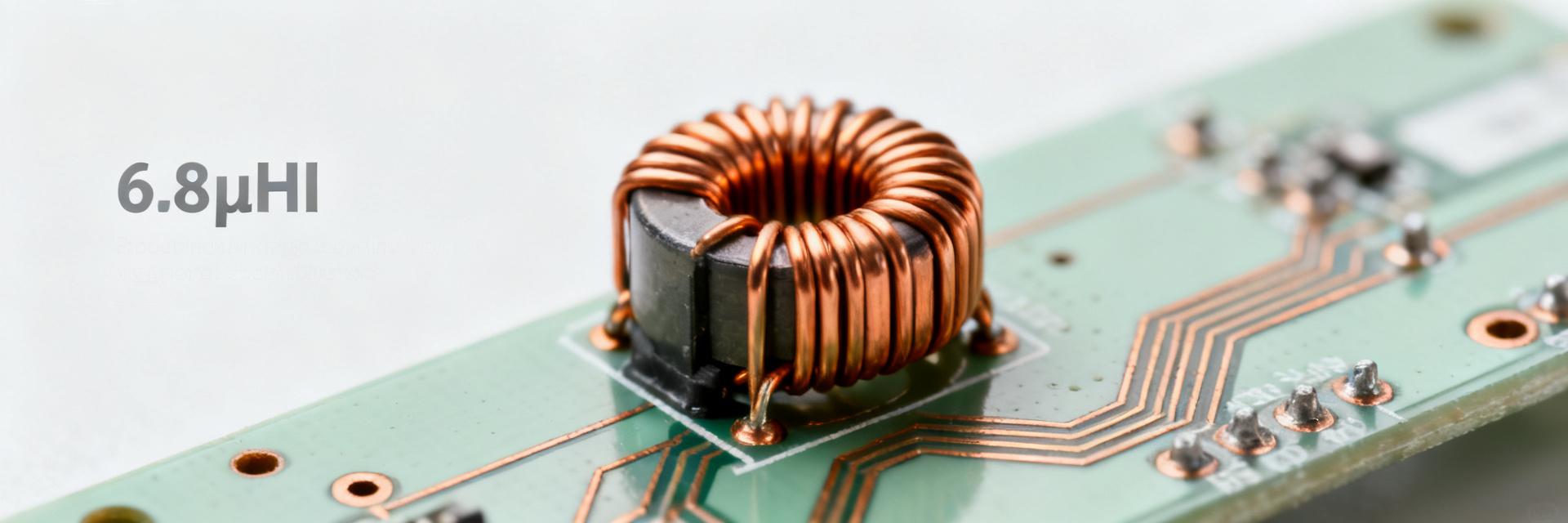
Point: the datasheet groups electrical and mechanical specs so designers can assess fit and function quickly. Evidence: core electrical entries include nominal inductance (6.8 µH), tolerance, rated current, saturation current, DC resistance (DCR), self‑resonant frequency (SRF) and test frequency. Explanation: each entry has a defined test condition (e.g., inductance measured at a specified test frequency and signal level); knowing those test conditions lets you compare parts fairly and apply the specs to your operating point.
Electrical & nominal specs to note
Point: key electrical specs tell you how the inductor will behave in the circuit. Evidence: inductance and tolerance define nominal reactance; rated current and saturation current limit usable current; DCR sets I²R loss; SRF and test frequency define high‑frequency behavior. Explanation: read the datasheet's test frequency (often 100 kHz or 1 MHz) to know the reference for nominal inductance and use inductance vs. frequency curves to predict impedance at your switching frequency.
Mechanical, mounting & environmental specs
Point: package, land pattern and thermal limits determine assembly and thermal path. Evidence: the datasheet provides package/size code, recommended land pattern, soldering temperature limits and storage/operating temperatures (−40 °C to +125 °C). Explanation: footprint and copper pour directly affect thermal dissipation and mechanical support; read the land‑pattern drawing to match pad dimensions and solder fillet guidance to avoid tombstoning or poor heat transfer during reflow.
2 & 3 — Performance & Handling Analysis
Electrical Performance: Inductance & SRF
Point: inductance vs. frequency and SRF curves in the datasheet determine usable bandwidth. Evidence: datasheet curves show inductance droop or rise with frequency and a clear SRF where inductive reactance crosses capacitive behavior. Explanation: use those curves to calculate effective impedance at the converter switching frequency and to decide whether the part behaves as an inductor or a resonant element in your filter.
Self‑resonant frequency (SRF): SRF is the limit where the part stops acting as a pure inductor. Above SRF the device becomes capacitive. Rule of thumb: remain at least an order of magnitude (a decade) below SRF.
Current Handling & DCR
Point: DCR and saturation jointly determine loss and peak current behavior. Evidence: the datasheet lists DCR (with tolerance) and often provides a saturation curve showing inductance vs. DC bias. Explanation: use DCR to estimate steady‑state I²R loss and the saturation curve to find the current at which inductance falls to a specified percentage of nominal; both influence thermal rise and converter stability.
Example calculation: If DCR = 0.08 Ω and rated current 2.4 A, P_loss ≈ (2.4 A)² × 0.08 Ω = 0.46 W.
4 & 5 — Application & Reliability
Thermal & Assembly Considerations
Point: soldering profile and temperature limits from the datasheet map to assembly actions. Evidence: soldering temperature and recommended reflow profile are specified; recommended pre/post‑bake and storage conditions may appear. Explanation: qualify the part with your chosen reflow profile, perform a wetting check on the specified land pattern, and include bake steps if the part is moisture sensitive; track any shift in inductance or DCR after thermal cycling as an aging indicator.
Typical Application: Buck Converters
Point: this part is suited for compact buck converters and power rails with moderate currents. Evidence: 6.8 µH and ~2.4 A rating indicate suitability for lower switching frequencies or as an output choke in small regulators. Explanation: selection rules — choose inductance so that ripple current meets your target (ΔI = Vout·(1−D)/(L·fs)); verify that DCR and saturation at peak current meet efficiency and EMC goals before approving the design.
6 — Design Validation Checklist
| Validation Metric | Target / Pass Criteria | Measurement Action |
|---|---|---|
| Inductance (L) | Within ±10% at operating frequency | Measure at switching frequency (fs) |
| DC Resistance | ≤ Datasheet max + tolerance | 4-wire Kelvin probe at ambient |
| Saturation (Isat) | > 1.2× worst-case peak current | Verify L-drop under DC bias |
| Thermal Rise | Temp rise | Infrared thermal scan on PCB |
Summary
When specifying the 784774068 power inductor prioritize the datasheet's inductance vs. frequency data, DCR and saturation/derating curves, and mounting/thermal guidance. Use the validation checklist to confirm performance in your PCB and thermal environment, and record pass/fail criteria in the BOM to avoid surprises during production.
- Verify inductance at your switching frequency and consult the datasheet specs for L vs. frequency to ensure required impedance and ripple suppression.
- Calculate I²R loss from DCR and rated current; confirm thermal rise is acceptable using PCB thermal modeling and bench measurements.
- Check the saturation curve and choose an operating current below both thermal and saturation limits for long‑term reliability.
- Follow the recommended land pattern and reflow limits from the datasheet to ensure mechanical stability and solder joint reliability.
- Document part number, datasheet revision and approved footprint in the BOM; verify alternates against inductance, DCR, SRF and mechanical fit.


